The Top Mitsubishi Galant VR-4 Resource

Join the best E39A 1991-1992 Mitsubishi Galant VR-4 community and document your GVR4 journey.

  • Software Upgraded - Reset Your Password to Login
    In order to log in after the forum software change, you need to reset your password. If you don't have access to the email address you used to register your GVR4.org account, you won't be able to reset your password. In that case, follow the instructions here to regain access to the forum.

Coil Packs and Dwell Time

TrevorS

Well-known member
Joined
Jul 26, 2012
Messages
49
Location
Newark, DE
Greets all /ubbthreads/images/graemlins/smile.gif! I continue to thank Roger and Brox for their genuine contribution to the community. Unfortunately, it would appear the community has minimal interest /ubbthreads/images/graemlins/frown.gif! Unless I see a significant turn around in interest in this forum, I'll be taking my further posts elsewhere. But to Roger and Brox, many thanks brothers /ubbthreads/images/graemlins/smile.gif!
 
Last edited:

JNR

Well-known member
Joined
Apr 23, 2004
Messages
9,814
Location
ca
Unfortunately, other than a few members here, the 'technical' part of this forum is pretty limited and we don't get into real discussions like some other boards. Seems a lot of the old timers have come and gone and the archives don't go back that far. There's still a few guys left though, but guess this is one of those subjects people aren't super interested in. As I mentioned, I'd like to hear more about alternative ignitions, although I don't feel the oem unit is *that* bad provided it works well and the COP seems to *work*, although I'm sure it can be imporved upon.
 

TrevorS

Well-known member
Joined
Jul 26, 2012
Messages
49
Location
Newark, DE
Yeah, time goes by /ubbthreads/images/graemlins/frown.gif! As far as COP working, I read of lots of people saying otherwise. Of course, the most obvious reason is not having the wiring correct for the model year, but I also see people reporting misfire issues at both casual throttle and boost. Seems like the typical solution is to shrink the plug gap, but at heavy boost, that doesn't usually solve it. The real solution for someone serious is the non-trivial cost of a CDI system to boost the COP primary voltage.

The way I view it, if you have to shrink the gap to make it work, then it doesn't really work -- there's a problem. Rogers' measurements make it pretty clear why there's a problem, and so changing from OE coil pack to COP is probably something to be careful about -- CDI is an investment. As you say, the OE system works, in fact it works well. My interest is in installing COP as a genuine upgrade from OE, not needing a band-aid to get by or additional investment. As an upgrade, I also care about the end result looking clean, reasonably professional.

It appears to me Brox has demonstrated the dual power transistor method works, though it's still imperfect. My hope is that by providing a stiff dedicated primary power line, healthy power transistor and COP wiring, plus a local shunt capacitor, it can be a true upgrade without the need for CDI. Kind of an ignition system redesign, rather than just a band-aid.
 
Last edited:

toybreaker

iconoclast
Joined
Apr 30, 2006
Messages
3,581
I can't speak for anyone else, but I know why I dropped interest in this project.


I did make a few posts in the thread when it was active, based on my real world, hands on experiences.

This was experience gained in converting points style cars over to H.E.I. systems. It involved many steps, including machining the shaft to accept a reluctor wheel, machining and indexing the breaker plate to accept a pick up coil, selecting a weight/spring package to dial in the ignition timing (and/or adding a load sensitive timing adjustment with vacuum advance/retard cans), fabbing up a harness, and finally, spec'ing out the coils.

... only to be told that my actual hand on experience was null and void because it doesn't matter which way the plug is fired.

wow!

Quoting belize1334:

As for the question of the spark going the wrong way over the plug. Unless you're dealing with an inherently directional material, such as a diode or a pnp junction, all of electricity, including currents, fields, potentials, plasma currents, etc, is invariant under interchange of sign. There is NO reason to expect that it should be harder to ionize the spark gap from the ground strap to the electrode than from the electrode to the ground strap.

To see that this MUST be the case, inspect the diagram for the OEM coils. Each coil only has ONE secondary coil and it connects to both spark plugs (one on each end). When it discharges the current flows down through on plug and up through the other to complete the path. The plugs themselves couldn't care less which direction the charge is flowing. In fact, I suspect that the discharge current is actually A/C and not D/C given that the oscillating field necessary to induce the breakdown voltage would have to be EXTREMELY FAST in order to build up to the necessary strength. That means that in the time it takes to discharge the spark the current over a single plug is likely switching direction over and over, making polarity an inapplicable concept.


Seems like they better take back the Noble Prize from a certain Mr Owen Richardson


I only know of this phenomenon because my grandfather let me build my own radio / experiment with vacuum tubes, and I got it wrong a couple of times.

... oh and a couple of hundred hours of watching raster patterns on vehicles while I dialed in various coil/condensor packages on home built H.E.I systems.

I'm especially proud of a crank fired set-up I built for the Datsun Z cars. It makes well over 50kv peak voltage! Got well over 300 thousand miles on that set-up. It's seen duty in four different chassis without a single component replacement other than caps and rotors.


... yeah, my real world experience is hardly relevant /ubbthreads/images/graemlins/idea.gif


I was lucky enough to work for some saavy cats that helped me every step of the way. They allowed me to use their distributor machines, their occiliscopes and most of all they gave me invaluable advice based on their experience.

These men did not suffer fools well, and yet they helped me.

I noticed they didn't help many folks, but they helped me


... as I get older, I'm beginning to really understand where they were coming from.


My wife says it's because I'm one humble cat.

I think it's because the more I know, the more I know I don't know,

... and I know when to give credit where credit is due.

... which is 24/7/365 ...


I like to help folks.

some folks get it

Nothing is more satisfying than hearing a motor run for the first time, or helping someone find an elusive gremlin.

None of us was born with the skills we have today.

We all started somewhere.

Some of the saaviest cats on here don't have good communication skills. Hell, they were too busy with women in school to pay much attention /ubbthreads/images/graemlins/devil.gif

Somewhere along the way, someone helped them gain the knowledge they now have.

I'm one of the lucky ones, as I've been blessed with a life long string of rock solid men who gave me guidance.

Most of those men have passed on /ubbthreads/images/graemlins/bawling.gif and the world is the poorer for it.


I try and pay them back by paying it forward.


... but I guess I'm turning into one of those grumpy old men because trying to help folks who talk down to me, or won't even let me know that the ignitor and pigtail arrived safely

... just takes all the "fun" out of things


In fact, this very thread is one of the reasons I don't post on this board much anymore


Carry on, gentlemen, carry on.
 
Last edited:

JNR

Well-known member
Joined
Apr 23, 2004
Messages
9,814
Location
ca
I hear ya, John and you are one of the few people I was referring to that actually know what they are talking about and not reciting things they 'heard' or saw on the internet. I too get talked down and made to sound like I don't know what I'm talking about and have been involved in this hobby for ~24 years now, dealt with a lot of good folks and tried to pick up as much as I can...There are many things I've forgotten or not worked on in many years, but I still try to give out whatever I know for no charge or never expecting anything in return. However, in this forum for the most part, I pretty gave up contributing too much in the technical part of things, as there's far more to life than arguing with those people who don't seem to want to anything but. It's a shame, cause at one time, it seemed there was a really good wealth of solid info/advice; still is some and you guys that know what you're talking about know who you are and glad you haven't given up completely.
 

toybreaker

iconoclast
Joined
Apr 30, 2006
Messages
3,581
... damn, what happened to your title? /ubbthreads/images/graemlins/devil.gif
 

JNR

Well-known member
Joined
Apr 23, 2004
Messages
9,814
Location
ca
lol, don't know...but it's funny /ubbthreads/images/graemlins/smile.gif
 

curtis

Well-known member
Joined
May 4, 2003
Messages
11,892
Location
Clarksville TN
/ubbthreads/images/graemlins/rofl.gif Humble /ubbthreads/images/graemlins/rofl.gif

all I can say is this...... Never Ever Never go toe to toe with the old bastards because because age and treachery beats out youth and enthusiasm everytime


Some thing else comes to mind as well. This makes me feel like I'm in the bar with these guys /ubbthreads/images/graemlins/grin.gif

"My boy Jon is wicked smaht."
 
Last edited:

TrevorS

Well-known member
Joined
Jul 26, 2012
Messages
49
Location
Newark, DE
Quoting toybreaker:

Nothing is more satisfying than hearing a motor run for the first time


Hoping to be there with my ignition mods pretty soon.
 

TrevorS

Well-known member
Joined
Jul 26, 2012
Messages
49
Location
Newark, DE
Quoting toybreaker:

The ignitors make some pretty substantial amounts of heat during operation, so while this might work ok for testing, I would try and mount the ignitors individually in the factory configuration with each of their backs against their own heat sink. Some heat transfer/dilectric grease applied between them and their respective heat sink surfaces would also increase their ability to transfer their operating heat out of the units.


Here is how I'm mounting the power transistor packs, they go in the spot once occupied by the OE coil pack.
EclipseCOPignition_1.jpg


Not too sure about how well silicon grease would work, the contact faces of the packs are very uneven. I tried sanding the faces with 600 grit on a hard flat surface and only the edges of three sides plus around the bolt openings are in contact. Not especially encouraging /ubbthreads/images/graemlins/frown.gif!

Quoting toybreaker:
Please note the coils are fed directly from the ignition switch down the same wire that feeds the fuel pump leg of the mpi relay. Increasing the current carried by the ignition switch may result in a significant shortening of it's service life. At the very least, it will result in some voltage drop out to the coils as well as the fuel pump. A separate dedicated relay used to feed your new coil circuit, located out in the engine compartment would probably be the mostest bestest way to work the supply side.


Install a dedicated coil power supply relay out in the engine compartment.
Feed it fused power from the battery down a quality ten gauge (or eight awg if youre feeling froggy)
Switch the relay on using the original black/white wire that used to power the coils.
(an interupt could be put on the ground leg of the relay as a hidden security feature...)

For the connections out to the coils, I would make a jumper harness that plugged into the original harness and then into the twin ignitor multiple coil harness, (leaving the option to go back to stock if the whiz bang shitarree lost it's desire to throw a spark)


I've run 10 AWG from the battery (15A fuse) to a firewall mounted relay followed by 12 AWG to the coil connector. I would have preferred to preserve the OE harness, but there's a lot of 16 AWG wire running around in it (significant lengths) and I'm already not happy with 16 for driving and powering the COP coils. I'm using the OE 14 AWG B/W to supply the transistor pack OR electronics and to operate the relay. Reason I'm powering the OR circuitry is that some electronics don't like it if part of their complete circuit is unpowered, it can result in leakage or even breakdown -- as mine is a '90, my OR is performed at the coils, so I use neither of the transistor pack outputs.


Quoting toybreaker:
It "appears" to my untrained eye that the ecu is just tickling one leg of a switching transistor in the igniter case when it wants to fire a coil.

It's this transistor located in the ignitor that will switch and carry the current that energises the coils. This means the ecu will only see the load that it takes to switch a transistor. The actual coil ground will run thru the legs of the ignitor transistor and out to ground on pin 3 (black wire) from the ignitor unit, not back thru the ecu.

I must say I don't completely understand how much loading the ecu "sees" when it triggers the transistor in the ignitor to fire the coils, but I do know it looks like we're preparing to double that load. To an uneducated mook like me it seems like we should be sure the ground traces from the ignitor triggers are up to the extra loading, and the actuall switching components are up to the task... long term ...


At any rate, I would probably optimise/upgrade the ground path out of the ignitors, as they will see higher loadings.


It appears to me the ECU is actually using a self protective pullup resistor to drive the power transistor packs. The biggest question being whether the resistor can provide enough current to drive the hoped for increase in total current. Tightening up the ground should definitely help this. The OE transistor pack ground wire is also 16 AWG and runs through the harness. I spliced the two transistor 16 AWG to a short 14 AWG and grounded it directly to the manifold. The manifold itself has a stiff ground to chassis on the firewall side.

Quoting toybreaker:

Good luck with the project, gentlemen, and please keep this thread updated. I like to see people try new things! /ubbthreads/images/graemlins/smile.gif


Thanks dude -- I appreciate your inputs /ubbthreads/images/graemlins/smile.gif!
 
Last edited:

TrevorS

Well-known member
Joined
Jul 26, 2012
Messages
49
Location
Newark, DE
In case anyone's interested, here's the OE Intrepid and 300M 2.7L and 3.5L ignition capacitor, one of which mounts adjacent a COP module on each of the two cylinder heads.

EclipseCOPignition_2.jpg


The printed rating is identical to the one in the OE coil-pack assembly (.47uF/250V), but the package is different. The ignition capacitor was $15 from the local Dodge establishment ($20 online), but no doubt cheaper at a junkyard /ubbthreads/images/graemlins/smile.gif!
 
Last edited:

toybreaker

iconoclast
Joined
Apr 30, 2006
Messages
3,581
Quoting TrevorS:


Not too sure about how well silicon grease would work, the contact faces of the packs are very uneven. I tried sanding the faces with 600 grit on a hard flat surface and only the edges of three sides plus around the bolt openings are in contact. Not especially encouraging /ubbthreads/images/graemlins/frown.gif!


As you've noticed, many standard silicone di-electric greases are kinda runny, and they don't fair well in may places under the hood. Being that thin makes them good for potting connections, but not so good as a heat transfer agent, where you want it to stay put forever.


I'm lucky enough to live in an area that has a kick-ass network of suppliers that service the aerospace industry, and I am constantly finding cool sh*t in the shops of the big dogs.

One other thing I like about the aerospace industry is they "time out" a lot of their chemicals, and screamin deals/freebies are often found if you know the right folks /ubbthreads/images/graemlins/smile.gif


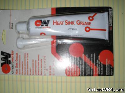
This product from Chemtronics is one of my favorites.


It's specifically a heat transfer agent.

It's thick, almost like a paste, and stays where you put it.

The working temperature range is -42* to 342* f, and I've found it to be stable in almost any condition you'll ever find in an engine compartment. It fills *fairly* large gaps, and it (or a suitable facsimile ) may be just the ticket for your application.

You can peruse the Chemtronics catalog here

You *might* also be able to find it (or a reasonable substitute) at a local electronics supply house. If it meets Mil-Spec C-4713, you've *probably* found the good stuff.

If you can't find it locally, I can send you some.

I got lots /ubbthreads/images/graemlins/rofl.gif

Quoting toybreaker:
Please note the coils are fed directly from the ignition switch down the same wire that feeds the fuel pump leg of the mpi relay. Increasing the current carried by the ignition switch may result in a significant shortening of it's service life. At the very least, it will result in some voltage drop out to the coils as well as the fuel pump. A separate dedicated relay used to feed your new coil circuit, located out in the engine compartment would probably be the mostest bestest way to work the supply side.


Install a dedicated coil power supply relay out in the engine compartment.
Feed it fused power from the battery down a quality ten gauge (or eight awg if youre feeling froggy)
Switch the relay on using the original black/white wire that used to power the coils.
(an interupt could be put on the ground leg of the relay as a hidden security feature...)

For the connections out to the coils, I would make a jumper harness that plugged into the original harness and then into the twin ignitor multiple coil harness, (leaving the option to go back to stock if the whiz bang shitarree lost it's desire to throw a spark)


Quoting TrevorS:
I've run 10 AWG from the battery (15A fuse) to a firewall mounted relay followed by 12 AWG to the coil connector. I would have preferred to preserve the OE harness, but there's a lot of 16 AWG wire running around in it (significant lengths) and I'm already not happy with 16 for driving and powering the COP coils. I'm using the OE 14 AWG B/W to supply the transistor pack OR electronics and to operate the relay. Reason I'm powering the OR circuitry is that some electronics don't like it if part of their complete circuit is unpowered, it can result in leakage or even breakdown -- as mine is a '90, my OR is performed at the coils, so I use neither of the transistor pack outputs.


Sounds like you're getting serious!

... also sounds like you're going to teach all a bit about the differences in the '90 ignition system.

That'll work out well for the folks who are converting ggsx's to turbo status. /ubbthreads/images/graemlins/smile.gif
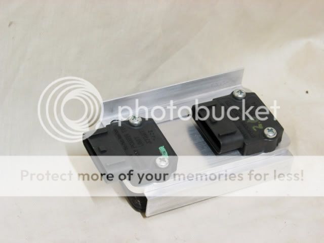
Quoting toybreaker:
It "appears" to my untrained eye that the ecu is just tickling one leg of a switching transistor in the igniter case when it wants to fire a coil.

It's this transistor located in the ignitor that will switch and carry the current that energises the coils. This means the ecu will only see the load that it takes to switch a transistor. The actual coil ground will run thru the legs of the ignitor transistor and out to ground on pin 3 (black wire) from the ignitor unit, not back thru the ecu.

I must say I don't completely understand how much loading the ecu "sees" when it triggers the transistor in the ignitor to fire the coils, but I do know it looks like we're preparing to double that load. To an uneducated mook like me it seems like we should be sure the ground traces from the ignitor triggers are up to the extra loading, and the actuall switching components are up to the task... long term ...


At any rate, I would probably optimise/upgrade the ground path out of the ignitors, as they will see higher loadings.


Quoting TrevorS:
It appears to me the ECU is actually using a self protective pullup resistor to drive the power transistor packs. The biggest question being whether the resistor can provide enough current to drive the hoped for increase in total current. Tightening up the ground should definitely help this. The OE transistor pack ground wire is also 16 AWG and runs through the harness. I spliced the two transistor 16 AWG to a short 14 AWG and grounded it directly to the manifold. The manifold itself has a stiff ground to chassis on the firewall side.


Sounds like you have a good grasp on things.

... much better than me! /ubbthreads/images/graemlins/rofl.gif

I grew up in an era of points/carbs, and even though I've studied the circuit diagrams, read the books, and really tried to understand things, I've always viewed electronic devices as vodoo down at the component level.

I grasp the concepts okay, but the specifics elude me.


I stOOpid that way, so if you could dumb it down a little for me, I'd appreciate it! /ubbthreads/images/graemlins/smile.gif


One concern I have is that they may be small/subtle timing differences between the various components.

Will a difference in the resistance/capacitance/inductive voodery of the various components that are being used in the parallel circuits cause any timing or feedback type problems?


Quoting TrevorS:


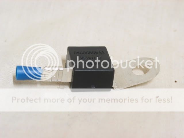
I case anyone's interested, here's the OE Intrepid and 300M 2.7L and 3.5L ignition capacitor, one of which mounts adjacent a COP module on each of the two cylinder heads.

EclipseCOPignition_2.jpg


The printed rating is identical to the one in the OE coil-pack assembly (.47uF/250V), but the package is different. The ignition capacitor was $15 from the local Dodge establishment ($20 online), but no doubt cheaper at a junkyard /ubbthreads/images/graemlins/smile.gif!


Nice find!

I like what you're doing here, Trevor.

Sourcing matching components is one of the "secrets" to making one off stuff work.

... please be sure to insulate that female terminal/connector where it plugs onto the condensor body well!

A little heat shrink over the whole terminal will do the trick.


Please keep the thread updated with your progress!
 

TrevorS

Well-known member
Joined
Jul 26, 2012
Messages
49
Location
Newark, DE
Just want to comment that I've had some positive responses and interesting inputs via PM and I'm appreciative. If I can be more fully responsive to questions (or perhaps just empathize /ubbthreads/images/graemlins/smile.gif), please feel free to post accordingly. My purpose is only to build on what was already provided within the thread and hopefully achieve a good result for my own DSM. With any luck, it'll prove helpful to others as well /ubbthreads/images/graemlins/smile.gif!

Moving on! John, it's been suggested I should proceed with leveling the heat dissipation surfaces of the transistor power packs. As I mentioned, I tried that manually with 600 grit and accomplished little. Do you by any chance know if this is practical? I can't afford to damage the packs (cost me over $20 apiece), but if it should be safe, I could touch them to my belt sander and then apply progressive hand sanding methods. I'm not used to electronic devices having such a terribly uneven surface, makes me think the design engineers had little concern about heat dissipation (perhaps justified?) And thanks for the dielectric compound offer, but given I still have some Radio Shack silver based compound from fooling with PC cpus, I'm guessing I'm OK.

I only mention my '90 tach signal function to help explain what I did with the transistor power pack OR outputs. I actually looked into the possibility of substituting the transistor signal for my coil OR, but turns out my OE tach unit is incompatible with post '90.

Seems clear you're not "stOOpid". Idea is that an internal ECU transistor can be safely controlled to pull down on an internal pull up resistor. In the pull down mode, no current is available to the outboard circuit, whereas with the transistor off, whatever current the pullup resistor is capable of providing is available to drive the outboard circuit (open-collector devices without resistors are also useful, though without a series resistor, the risk is greater). This design technique normally eliminates likelihood of internal device damage, though it requires understanding of external current demands. Generally, a reasonable percentage greater current is made available then the external circuit should require. I would expect the modest additional requirement for series Intrepid coil inductance (about 16% for energy match) to be easily within margin. My expectation is a design margin of 25% would also be covered, but a solid transistor pack ground would likely be required, problem being current flow tends to consume available voltage (wire has resistance /ubbthreads/images/graemlins/frown.gif)! So, I'm trying to reasonably minimize the influence of wire as a significant factor.

I wouldn't expect there to be timing issues. Electronics with reasonable wiring operates on the order of microseconds and less, whereas the coils can't begin to respond in that time frame. At worst is the mentioned issue of the two transistor power packs not actually being equivalent. It's pretty much guaranteed that one will conduct current well before the other, but all that matters is whether the other at least reasonably catches up as the junction and resistive semiconductor voltage builds. I don't see an issue with having an ampere or so difference between them at max flow, and the driven coil will certainly not care, besides, it takes time for the current to build (the dwell angle or duty cycle factor), whereas transistor shut down should be roughly equally quick between them.

I can't help but consider the ignition capacitor to be an important factor in optimal ignition operation. I spent a fair amount of time tracking down the Intrepid capacitor (located and downloaded the service manual, studied the contained info, and engaged in net searching to track it down.) I suspected the OE capacitor was likely the same value, but it's not available as a separate part and I wasn't certain. This way I don't have to partially disassemble the OE coil pack, I'm certain of the correct value, and if there's a failure of the Intrepid part, I can easily replace it.

Lastly, thanks for chiming in /ubbthreads/images/graemlins/smile.gif!
 

TrevorS

Well-known member
Joined
Jul 26, 2012
Messages
49
Location
Newark, DE
By the way, I'm a little uncertain whether to call you John or Jon. If Jon is correct, please accept my apology /ubbthreads/images/graemlins/frown.gif!
 

toybreaker

iconoclast
Joined
Apr 30, 2006
Messages
3,581
Quoting TrevorS:
it's been suggested I should proceed with leveling the heat dissipation surfaces of the transistor power packs.


I would not recommend that.


Those wiley engineers put that recessed area in there for a reason.

... maybe to allow for expansion/contraction of the base plate as the unit thermally cycles. /ubbthreads/images/graemlins/dunno.gif

At any rate, with the correct heat transfer agent in between the case and your heat sink/mounting plate, you should be good to go, no mods to the base plate required.


I don't want to take this thread any further off topic than I already have, but there's a point here that must be addressed


Trevor, there's some really saavy guys on this board.

They know component level electronics well, as that's what they do for a living.

Why they never posted in this thread I do not know. /ubbthreads/images/graemlins/dunno.gif


I can't speak for them

... only myself.

All I can do is ask "theory" type questions on topics like this.

I know a "bit" about practical applications and how to screw sh*t up, as that's something I have done as a tech. ( lots /ubbthreads/images/graemlins/rofl.gif )

I usually leave the theory/component level stuff to the boffins, as that's what they do for a paying gig.

When I find saavy guys, I'll bombard them with questions

... Lots and lots of questions ... /ubbthreads/images/graemlins/rofl.gif

The ones I respect will say "I don;t know" when asked something that's outside their scope/experience/comfort zone.

Usually, they'll ask their go-to guy/mentor, and get back to me with a legitimate answer, and we all learn something.


nobody knows everything


Me, I'm just a practical applications guy.


There are some other practical application guys on here.

Curtis and BosstX (as well as several others) come to mind when c.o.p. systems come up

They both make some really clean plates, and have wired a whole sh*t ton of the "standard" style systems, with very few problems.

... can;t speak for them, but I don't think either of them like being talked down to either.

... don;t think they have had many wiring problems with their work!

(well, maybe Curtis has, it's hard to get all those wire nuts to fit under the plate /ubbthreads/images/graemlins/fawkd.gif )


The things is there's folks who don;t mind stepping outside their comfort zone and admitting their ignorance when venturing into virgin territory, if it will contribute to the knowledge pool/further a project.

... but once you start making them feel stupid, you'll lose their input forever.


... and good threads like this wither and die.


Gotta wrap this up, as work beckons.


But, here's something to think about

Somewhere at NASA, some guy came up with the "sky-crane" concept for safely placing the rover on Mars.

That's some seriously zany, sh*t right there!

... but it flat worked

Thinking outside the box is where innovation/progress comes from.

But, no smart man does sh*t alone.

I'm sure the brainiacs there bounced that sh*t off each either for quite some time, and they probably asked for and got input from the guys on the shop floor.

They are the guys with the practical knowledge of the hardware that makes their pipe dreams a reality.

That's what makes a good team.

The synergy between the boffins and the practical guys.

Make the shop level guys feel stupid, and you lose their input.


... it really is that simple ... /ubbthreads/images/graemlins/smile.gif
 

JNR

Well-known member
Joined
Apr 23, 2004
Messages
9,814
Location
ca
Just wanted to second that the heatsink compound (paste) works really well and I was amazed on my CPU at home the difference a little bit of that stuff made on the processor to heatsink. I bought it at the local electronics supply house (not radio shack) and it was pretty $$ there for a tiny amount, so I'd suggest looking online, or if you ahve a Fry's nearby, etc.

Remember with heat transfer that while you want to get the heat out from the offending device (i.e. power transistor) and disperse it to a mating material (i.e. aluminum or copper [better] heatsink), you need to promote airflow somehow to direct the heat off that material (heatsink)...Those probably don't produce enough heat to warrant a dedicated fan if you can get enough material mass, but just remember not to install it upside down and all that.
 

belize1334

Well-known member
Joined
Nov 18, 2003
Messages
3,316
Location
Bozeman, MT
Sorry for my lack of participation in this conversation. I'm no longer running COP and I've been traveling alot this summer so that's taken alot of my time.

The directionality of the spark may be worth discussing in principle but the fact is that the OEM configuration already runs two of the spark plugs in the reverse polarization. But wiring the COP to operate in current loop pairs and reversing the polarization of two of the coils we actually mimic the OEM behavior. A quick look at the FSM should be enough to convince anyone of this fact. And the Chrysler coils work perfectly well in this configuration as I ran them that way for quite a while with no problem.

As for the igniters. I think it's just a matter of having the total impedance such that there is sufficient energy in the spark and not too long of a charge time. After that it's a matter of not overloading the power circuit, facilitated by running twin igniters with a dedicated power source.
 

TrevorS

Well-known member
Joined
Jul 26, 2012
Messages
49
Location
Newark, DE
Quoting toybreaker:
Quoting TrevorS:
it's been suggested I should proceed with leveling the heat dissipation surfaces of the transistor power packs.


I would not recommend that.

Those wiley engineers put that recessed area in there for a reason ... maybe to allow for expansion/contraction of the base plate as the unit thermally cycles. /ubbthreads/images/graemlins/dunno.gif

At any rate, with the correct heat transfer agent in between the case and your heat sink/mounting plate, you should be good to go, no mods to the base plate required.


Guess I didn't frame my question very well /ubbthreads/images/graemlins/frown.gif! I understand your disagreement with grinding down to the well, but I was actually thinking of the upper level, which is itself highly uneven. However, I can't easily believe the engineers weren't aware of that production short-fall and so it's either an opportunity for us folks, or a doesn't-matter and the engineers knew it. If it's a doesn't matter, I can understand why they used a stamped steel heat sink on those things.

Quoting toybreaker:

Trevor, there's some really saavy guys on this board. They know component level electronics well, as that's what they do for a living. Why they never posted in this thread I do not know. /ubbthreads/images/graemlins/dunno.gif I can't speak for them ... only myself. All I can do is ask "theory" type questions on topics like this. I know a "bit" about practical applications and how to screw sh*t up, as that's something I have done as a tech. ( lots /ubbthreads/images/graemlins/rofl.gif ) I usually leave the theory/component level stuff to the boffins, as that's what they do for a paying gig. When I find saavy guys, I'll bombard them with questions ... Lots and lots of questions ... /ubbthreads/images/graemlins/rofl.gif


The ones I respect will say "I don't know" when asked something that's outside their scope/experience/comfort zone. Usually, they'll ask their go-to guy/mentor, and get back to me with a legitimate answer, and we all learn something. nobody knows everything Me, I'm just a practical applications guy. There are some other practical application guys on here. Curtis and BosstX (as well as several others) come to mind when c.o.p. systems come up. They both make some really clean plates, and have wired a whole sh*t ton of the "standard" style systems, with very few problems. ... can't speak for them, but I don't think either of them like being talked down to either. ... don't think they have had many wiring problems with their work! (well, maybe Curtis has, it's hard to get all those wire nuts to fit under the plate /ubbthreads/images/graemlins/fawkd.gif )

The things is there's folks who don't mind stepping outside their comfort zone and admitting their ignorance when venturing into virgin territory, if it will contribute to the knowledge pool/further a project. ... but once you start making them feel stupid, you'll lose their input forever ... and good threads like this wither and die. Gotta wrap this up, as work beckons. But, here's something to think about:

Somewhere at NASA, some guy came up with the "sky-crane" concept for safely placing the rover on Mars. That's some seriously zany, sh*t right there ... but it flat worked Thinking outside the box is where innovation/progress comes from. But, no smart man does sh*t alone. I'm sure the brainiacs there bounced that sh*t off each either for quite some time, and they probably asked for and got input from the guys on the shop floor. They are the guys with the practical knowledge of the hardware that makes their pipe dreams a reality. That's what makes a good team. The synergy between the boffins and the practical guys. Make the shop level guys feel stupid, and you lose their input ... it really is that simple ... /ubbthreads/images/graemlins/smile.gif


My interpretation of your message here is that I shouldn't be afraid to acknowledge what I'm uncertain of and I shouldn't be afraid to say I don't know. I've given the best information I can and have been trying to portray it honestly. If you feel I'm misleading people, by all means invite others to evaluate what I've said. Personally, I'm rarely dead sure of anything until I observe confirmation -- before that it's theory. I don't question your obvious experience with vehicles and I hope you'll point out whatever I say that is clearly incorrect. Although I do have some background in electronics, I'm surely still learning regarding cars.
 
Last edited:

TrevorS

Well-known member
Joined
Jul 26, 2012
Messages
49
Location
Newark, DE
Quoting JNR:
Just wanted to second that the heatsink compound (paste) works really well and I was amazed on my CPU at home the difference a little bit of that stuff made on the processor to heatsink. I bought it at the local electronics supply house (not radio shack) and it was pretty $$ there for a tiny amount, so I'd suggest looking online, or if you ahve a Fry's nearby, etc.

Remember with heat transfer that while you want to get the heat out from the offending device (i.e. power transistor) and disperse it to a mating material (i.e. aluminum or copper [better] heatsink), you need to promote airflow somehow to direct the heat off that material (heatsink)...Those probably don't produce enough heat to warrant a dedicated fan if you can get enough material mass, but just remember not to install it upside down and all that.


Yeah, it takes very little, you want as thin a layer as you can manage, which is why I'm uncomfortable using it to fill gaps between the heat sourcing device and the heat sink. To me, that's a situation where the surfaces need to be leveled before applying dielectric compound. These vehicles are mass produced and sold for far less than the potential cost if custom manufactured. Production short cuts tend to be the norm and I suspect these power transistor packs are a perfectly good example /ubbthreads/images/graemlins/frown.gif.

I installed copper heat sinks on a couple or three of my graphics cards and they were very effective, but aluminum is also very good for the job (and less expensive), certainly far more effective than steel. I originally designed my heat sink with the '90 power transistor packs in mind, but it turned out the '91+ are larger and so I had to rework it. I would have preferred to keep another 1/4" or so at the bottom of mine (to match with the angle fin), but what's done is done. It's still a respectable step beyond the OE stamped steel.

I'm depending on a combination of convection and turbulence to get cooler air to flow both under and over the heat sink and past the fins, which are expected to both increase dissipation and help guide air flow. Guess I won't know how well it works until I've had a chance to see -- one of those time-will-tell situations.
 

TrevorS

Well-known member
Joined
Jul 26, 2012
Messages
49
Location
Newark, DE
Quoting belize1334:
As for the igniters. I think it's just a matter of having the total impedance such that there is sufficient energy in the spark and not too long of a charge time. After that it's a matter of not overloading the power circuit, facilitated by running twin igniters with a dedicated power source.


That's my primary concern, in increasing the current to match and exceed the OE coil energy (squared relationship), I'm also increasing the heat dissipation in the COP modules. Since I've no convenient way to ease back the duty cycle, I can only hope I don't exceed the COP module reliability specs -- another time-will-tell situation. Turns out the Intrepid coils support a standard Dodge 2.7L/3.5L spark gap of around .052", so they are clearly capable of storing healthy energy. We don't seem to need as much with our DSM standard gap and I'm hopeful this approach will work out fine.
 
Support Vendors who Support the GVR-4 Community
Boosted Fabrication ECM Tuning ExtremePSI Fuel Injector Clinic Jacks Transmissions JNZ Tuning Kiggly Racing Morrison Fabrications RixRacing RockAuto RTM Racing STM Tuned
Top