The Top Mitsubishi Galant VR-4 Resource

Join the best E39A 1991-1992 Mitsubishi Galant VR-4 community and document your GVR4 journey.

  • Software Upgraded - Reset Your Password to Login
    In order to log in after the forum software change, you need to reset your password. If you don't have access to the email address you used to register your GVR4.org account, you won't be able to reset your password. In that case, follow the instructions here to regain access to the forum.

Need help adding resistance to turn signals

PreskitVR4

Well-known member
Joined
Jun 28, 2008
Messages
272
Location
Prescott, Northern AZ
Heres what I did. I got some pigtails from the J-yard to turn the front of my OE corners into turnsignals. I ripped the printed circuits out, but the problem remain that an 1157 bulb is a bigger resistor than the 168 bulb that is doing it's job now. What's the easiest way to find and add this resistance so my flasher isn't on crack anymore. Thanks.
 

gramkrakr89

Well-known member
Joined
Jan 25, 2010
Messages
308
Location
Bunker Hill, WV
you can add a load resistor in parallel with the light bulb to pull the total resistance down to the correct level, but it would heat up substantially.

How much of a difference in resistance are we talking here?
-----
EDIT: Wow, forgive my not-reading-the-post-ness...

using an ohm-meter, measure the resistance of the original turn-signal bulb filament...

measure the resistance of the filament of the corner bulb that you'll be using instead...

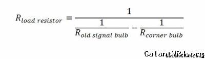
Then find the value of a load resistor to put in parallel with the corner bulb. The equation you'll want to use for this is as follows...


placing a resistor (of the value found using this equation) in parallel with the corner bulb will make a circuit equivalent to the original turn-signal bulb

you can use the closest standard value available in a common series and it should still work decently well... be sure to get a resistor designed to dissipate sufficient power or it'll heat up and melt! (your load resistor will need to handle more power than the bulb itself in most cases!)

measure the resistance of the 2 bulbs and post the results here
 
Last edited:

PreskitVR4

Well-known member
Joined
Jun 28, 2008
Messages
272
Location
Prescott, Northern AZ
Thats what I need to find out. I have a DVOM, but am ignorant on how to use it. I need to find out how to measure the resist. of the original 1157 bulb vs the new 168 bulb, and then the remedy, thanks.
 

gramkrakr89

Well-known member
Joined
Jan 25, 2010
Messages
308
Location
Bunker Hill, WV
please revisit the above post - I edited... sorry about not answering your question in the first place /ubbthreads/images/graemlins/frown.gif ...

to use the DMM, set the meter to resistance (Ohms, greek letter "omega"), and touch one lead to one bulb terminal, and the other lead to the other bulb terminal at the same time. If it is not auto-ranging, you will have to adjust the range until the meter gives you a good value instead of a {short} or {---} value... I'm sure google has a better explanation somewhere
 
Last edited:

PreskitVR4

Well-known member
Joined
Jun 28, 2008
Messages
272
Location
Prescott, Northern AZ
Thank you! Dies the resistor need to go "in line" on the wire, or does it need to go parallel with the bulb?
 

gramkrakr89

Well-known member
Joined
Jan 25, 2010
Messages
308
Location
Bunker Hill, WV
the load resistor will need to go in parallel with the bulb - your problem is that the original turn signal bulb allows more current to flow through it than the smaller corner bulb, right?

so allowing more current to flow around the corner bulb through a load resistor, you can simulate having the original turn signal bulb in the circuit.
 

PreskitVR4

Well-known member
Joined
Jun 28, 2008
Messages
272
Location
Prescott, Northern AZ
I thought most flasher units were universal, same. It would make sense though that a crew cab dually with 10,000 lights and 24 feet of wire would have a different flasher than a geo metro, thanks.
 

RedTwo

Well-known member
Joined
Jul 16, 2008
Messages
1,917
Location
New Zealand
Are you sure it's the bulbs resistance and not the 'broken turn signal' flash? /ubbthreads/images/graemlins/dunno.gif
 

467

Well-known member
Joined
Mar 16, 2001
Messages
919
Location
Fremont Ca
I added a 2 meg trim pot in series with resistor 2 in the relay.
You can adjust any flasher rate you want.
It takes some skill to put it under the relay case, see pictures.


img.php


img.php
 

467

Well-known member
Joined
Mar 16, 2001
Messages
919
Location
Fremont Ca
I think I used a 3/8" square pot. You can get 1/4" square too. There are all sorts of lead orientations. I used one like this click so I could bend one side of the lead to keep it from touching the board. I unsoldered the right hand end of R2 (looking at it from the orientation of the last picture) and stood it vertically behind the pot. Then I soldered one lead of the pot to the old solder hole in the board and one lead to the free end of R2. I glued the pot to the board for stability. There isn't much room there. I may have had to extend and bend the lead of R2 (possibly by taking R2 out to measure it and getting a new resistor) that goes to the board to get it behind the pot. It's been so long I don't remember exactly.

If I recall properly R2 was 220K OHMS. I could have just done without R2 and soldered in directly a 2.2 Meg pot. I don't know why I did it the way I did if that is correct.
 
Last edited:

PreskitVR4

Well-known member
Joined
Jun 28, 2008
Messages
272
Location
Prescott, Northern AZ
Ok soo, the smaller bulb has more resistance! So that means I need to take resistance out by either adding a bulb, or some how creat a path in the circuit with less resistance?
 
Support Vendors who Support the GVR-4 Community
Boosted Fabrication ECM Tuning ExtremePSI Fuel Injector Clinic Jacks Transmissions JNZ Tuning Kiggly Racing Morrison Fabrications RixRacing RockAuto RTM Racing STM Tuned
Top