The Top Mitsubishi Galant VR-4 Resource

Join the best E39A 1991-1992 Mitsubishi Galant VR-4 community and document your GVR4 journey.

  • Software Upgraded - Reset Your Password to Login
    In order to log in after the forum software change, you need to reset your password. If you don't have access to the email address you used to register your GVR4.org account, you won't be able to reset your password. In that case, follow the instructions here to regain access to the forum.

Fuel Pump Relay Fried

RedTwo

Well-known member
Joined
Jul 16, 2008
Messages
1,917
Location
New Zealand
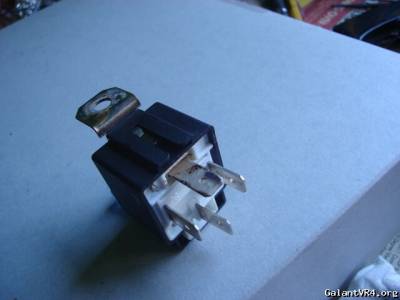
I rewired my fuel pump as per VFAQ (aside from using a SPST over a SPDT), everything was well and good for over a year until the other day I managed to kill the relay. Terminal 87 is pretty fried but the 15A fuse (across terminal 30) and the other terminals are untouched.
I've had a quick check through all the wires people have suggested before (o2, MPI relay, etc) and they all look good. I reconnected the wires from 86 and 87 and the car fired up.

Can anyone explain why 87 (to fuel pump) fried before the terminal and/or fuse coming off the battery did? Would this mean that the car/pump was actually running when the relay blew?
 

toybreaker

iconoclast
Joined
Apr 30, 2006
Messages
3,581
What was the relay rated at?

It may be as simple as the relay contacts got oxidized and the increased `resistance created enough heat to melt the terminal. /ubbthreads/images/graemlins/dunno.gif

For what it's worth, I've seen issues with the potter brumfield brand relays in that application. They just don't seem to hold up to the continuous duty that a fuel pump application requires.

I'd fire in a 40 amp rated Bosch unit, and call it done...

If the cause of the failure is still bugging you, open up the old relay and shoot a few pics. That'll tell the tale.

You can also measure the fuel pump current draw, as the other potential cause for that type of failure is a pump on it's way out. (Many pumps will draw extra amperage when they are on their last legs.)

edit Do you have an anti-fly back diode installed in this circuit?
 
Last edited:

FlyingEagle

Staff member
Joined
Mar 5, 2005
Messages
1,635
Location
THE Ottawa
Quote:
edit Do you have an anti-fly back diode installed in this circuit?


A wigywho? This sounds like a good idea, but what does it do?
 

toybreaker

iconoclast
Joined
Apr 30, 2006
Messages
3,581
Quote:
Quote:


edit Do you have an anti-fly back diode installed in this circuit?


A wigywho? This sounds like a good idea, but what does it do?


/silly,

it prevents issues with Musca Domestica Linneaus entering teh fuel system and wreaking havoc with teh fuel trimmage... /ubbthreads/images/graemlins/wink.gif

//silly

Actually, don't feel bad, I didn't know about this little device for years. /ubbthreads/images/graemlins/blush.gif

I always wondered why I was burning up relays and switches, when I thought I had properly rated them, (or in the case of electric motors, over-rated them by a factor of three).

The contacts of the switches would be all burned/pitted, and over time, the resistance of the contact point set would increase to the point that the circuit cease to operate consistently.

I was lucky enough to encounter a saaavy old school guy and he explained a few things in plain and simple language that even I could understand.

It seems that when an electric motor is operating, a magnetic field is created in the windings. (that's what attracts/repels the magnet segments on the rotor and makes it spin)

When the current is switched off, the magnetic field collapses.

This induces a counter electromotive force, or a power surge in the opposite direction of the original current flow.

This sends a power spike back up the wire. (The concept is very similiar to how a secondary circuit in an ignition coil works.)

This spike will arc/jump across the contact points in the relay/switch like a little lightning bolt, and over time, it will erode/damage the surface of the points.

Installing a suitably sized diode (or capacitor) in the circuit will shunt that power spike to ground, saving the points from the constant arcing.

This will prolong their service life considerably. /ubbthreads/images/graemlins/smile.gif

Many of the higher end relays, (and most bosch 4 pin relays) have this feature built in, but many of the cheaper and/or car stereo type relays don't have them, and you will need to an install one yourself.
 
Last edited:

FlyingEagle

Staff member
Joined
Mar 5, 2005
Messages
1,635
Location
THE Ottawa
Oddly enough we just learned about this in our first autmotive electrical classes.
It was called a clamping diode, but that is neither here nor there as it does the same thing. Current and or voltage will run around in a circle in the device until it's gone, or low enought to not cause said spike back into sensitive devices. I wonder if my fuel pump relay kit was supplied with a good relay. EEP!
 

iceman69510

Turn Right Racing
Staff member
Joined
Mar 5, 2001
Messages
10,964
Location
Michigan
Quoting toybreaker:
Quote:
Quote:


edit Do you have an anti-fly back diode installed in this circuit?


A wigywho? This sounds like a good idea, but what does it do?


/silly,

it prevents issues with Musca Domestica Linneaus entering teh fuel system and wreaking havoc with teh fuel trimmage... /ubbthreads/images/graemlins/wink.gif

//silly

Actually, don't feel bad, I didn't know about this little device for years. /ubbthreads/images/graemlins/blush.gif

I always wondered why I was burning up relays and switches, when I thought I had properly rated them, (or in the case of electric motors, over-rated them by a factor of three).

The contacts of the switches would be all burned/pitted, and over time, the resistance of the contact point set would increase to the point that the circuit cease to operate consistently.

I was lucky enough to encounter a saaavy old school guy and he explained a few things in plain and simple language that even I could understand.

It seems that when an electric motor is operating, a magnetic field is created in the windings. (that's what attracts/repels the magnet segments on the rotor and makes it spin)

When the current is switched off, the magnetic field collapses.

This induces a counter electromotive force, or a power surge in the opposite direction of the original current flow.

This sends a power spike back up the wire. (The concept is very similiar to how a secondary circuit in an ignition coil works.)

This spike will arc/jump across the contact points in the relay/switch like a little lightning bolt, and over time, it will erode/damage the surface of the points.

Installing a suitably sized diode (or capacitor) in the circuit will shunt that power spike to ground, saving the points from the constant arcing.

This will prolong their service life considerably. /ubbthreads/images/graemlins/smile.gif

Many of the higher end relays, (and most bosch 4 pin relays) have this feature built in, but many of the cheaper and/or car stereo type relays don't have them, and you will need to an install one yourself.


I love this place.
 

ktmrider

Well-known member
Joined
Sep 10, 2007
Messages
3,128
Location
Tempe, AZ
LOL, good description IMO...
Here is a great link click that covers exactly what the others are talking about ( altho they call it a "Quenching" diode ).
 

89coltgt

Well-known member
Joined
Mar 14, 2006
Messages
1,027
Location
Ste Genevieve, MO
They also call it a freewheeling diode.

click
 
Support Vendors who Support the GVR-4 Community
Boosted Fabrication ECM Tuning ExtremePSI Fuel Injector Clinic Jacks Transmissions JNZ Tuning Kiggly Racing Morrison Fabrications RixRacing RockAuto RTM Racing STM Tuned
Top