Hello,
I'm cleaning up some wiring on my car and now I'm to the ECU and have a few newb questions. From a previous owner the car has ECMLink V3, and Innovate LC-2 wideband and that is the wiring I'm looking at. I have read up on ECMLink, and just need some further clarification.
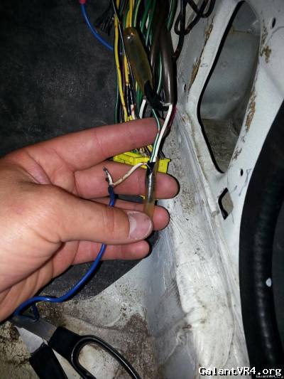
Blue wire that is connected to the white in this picture is the "Brown wire" from the wideband. So that seems to line up with the install instructions on ECMLinks website if you are wiring it into pin 4, the factory o2 sensor location. My question here is, wouldn't you replace the white wire from the factory o2 instead of connecting them both? And then simulate the narrowband with link? Or do I not understand the installation correctly. The car does still have the factory 02 sensor in the stock location, and then the wideband is downstream. If I want to continue to run both o2 sensors, shouldn't I hook the wideband's brown wire up to pin 15 (EGR)?
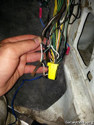
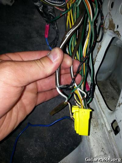
On this second picture you can see there is a green with white stripe wire soldered to the factory white o2 wire. I'm not sure what is going on here. On the Pinout cheat sheet the only two that are green and white is the Resistor (MAF) and TPS sensor. This was done by someone right? I haven't had to mess with the wiring before so I've never looked at a stock one. The car is running speed density, but it is connected using their cable to the stock mas connector. Not sure if that would matter, just trying to provide as much information as I can.
Last one, this can be seen in this picture (and the one above). The 2 black wires that are connected, one is solid black and is in the brown tube with the solid white wire, and the other is black with red lines. Do I want them connected? They are now.
I could be wrong on what wire is what so any help is greatly appreciated!! I can also take more pictures if needed for clarification. Thanks guys!
I'm cleaning up some wiring on my car and now I'm to the ECU and have a few newb questions. From a previous owner the car has ECMLink V3, and Innovate LC-2 wideband and that is the wiring I'm looking at. I have read up on ECMLink, and just need some further clarification.
Blue wire that is connected to the white in this picture is the "Brown wire" from the wideband. So that seems to line up with the install instructions on ECMLinks website if you are wiring it into pin 4, the factory o2 sensor location. My question here is, wouldn't you replace the white wire from the factory o2 instead of connecting them both? And then simulate the narrowband with link? Or do I not understand the installation correctly. The car does still have the factory 02 sensor in the stock location, and then the wideband is downstream. If I want to continue to run both o2 sensors, shouldn't I hook the wideband's brown wire up to pin 15 (EGR)?
On this second picture you can see there is a green with white stripe wire soldered to the factory white o2 wire. I'm not sure what is going on here. On the Pinout cheat sheet the only two that are green and white is the Resistor (MAF) and TPS sensor. This was done by someone right? I haven't had to mess with the wiring before so I've never looked at a stock one. The car is running speed density, but it is connected using their cable to the stock mas connector. Not sure if that would matter, just trying to provide as much information as I can.
Last one, this can be seen in this picture (and the one above). The 2 black wires that are connected, one is solid black and is in the brown tube with the solid white wire, and the other is black with red lines. Do I want them connected? They are now.
I could be wrong on what wire is what so any help is greatly appreciated!! I can also take more pictures if needed for clarification. Thanks guys!
