The Top Mitsubishi Galant VR-4 Resource

Join the best E39A 1991-1992 Mitsubishi Galant VR-4 community and document your GVR4 journey.

  • Software Upgraded - Reset Your Password to Login
    In order to log in after the forum software change, you need to reset your password. If you don't have access to the email address you used to register your GVR4.org account, you won't be able to reset your password. In that case, follow the instructions here to regain access to the forum.

Tubular Intake

mountaineerjeff

Well-known member
Joined
Oct 21, 2008
Messages
1,155
Location
west virginia
So there is an obvious advantage of working on air flow on a motor. this explains the indepth work on exhaust manifolds. tubular, equal length, and even divided housings.
Now why havent we applied this to the intake? I know that the longer the more bottom in, shorter the more top end. but what about the fact that the TB is much farther away from the 4th runner than the first? Maybe Im missing some sort of Intake technical design issue, but to me it seems like an equal length or at least tubular intake would flow better and give better power results.

Like I said forgive me if im ignorant on this one. I just kinda came up with this while thinkin bout the vr4.
 

onesickcrx

Well-known member
Joined
Jun 3, 2007
Messages
1,076
Location
NY
ITB's /ubbthreads/images/graemlins/grin.gif

AMS's new mani and Mangus's new mani are made to help it flow all four pretty close to the same flow. HKS mani is nice too
 

curtis

Well-known member
Joined
May 4, 2003
Messages
11,892
Location
Clarksville TN
Not to sound like an butthole but there's alot more that can be done than just a log plenum with 4 runners do some reading on Helmholtz ram effect on google.
 

mountaineerjeff

Well-known member
Joined
Oct 21, 2008
Messages
1,155
Location
west virginia
well what I gathered is an equation that seems to solve the issue on plenum volume and runner length. this could then be used to make the 'perfect' manifold. I how ever am asking about completely redesigning the manifold, not perfecting what we have. And while using this, it seems that if we increase Z2 then we could then decrease V and allow room for multiple TBs. One thing left out though is the distance between the valves and the end of the secondary pipes. This is where I figured an equal length setup would be better.

The only thing that would seem to oppose that is considering that the distance would be negligible because the system is pressurized. But even then on our standard I.M. the distance that the air has to travel between the TB+1valve and the distance of the TB+4valve seems large enough to make a difference, especially considering the speed of the valves. I feel Like alot of the design behind exhaust manifolds could also increase performance when applied to the Intake.

It also seems like if L1 is increased then V can also be decreased. so we could then be able to get rid of the plenum all together. Which would decrease the difficulty of running a dual TB system. The 2 TBs could be used to greatly increase A2 and in theory allow extremely short or long runners for torque or top end, or with a simple valve running off the tach recreate something like the cyclone setup.

like I said to begin with be nice, im just goin on limited knowledge here
 

gtluke

Well-known member
Joined
Sep 16, 2001
Messages
4,210
Location
dirty jersey
The problem is that the concept of flow pretty much goes out the window when under boost. If your intake is at 20psi your exhaust housing is usually about 40psi
 

mountaineerjeff

Well-known member
Joined
Oct 21, 2008
Messages
1,155
Location
west virginia
exactly, so if there is noticeable improvement in power from equal length tubular headers which are under pressure, then that should help my theory on applying these results to the IM
 

belize1334

Well-known member
Joined
Nov 18, 2003
Messages
3,316
Location
Bozeman, MT
We do have equal length runners. The issue of where the TB is located is largely negated by having a plenum of sufficient volume that the volume of air in the plenum is "significant" compared to the volume or air in the runners.
 

DR1665

Well-known member
Joined
Oct 19, 2005
Messages
4,642
Location
Iowa City, IA
Random: Suppose someone were to come up with an equal length runner intake manifold sporting individual Gixxer TBs atop each runner. Enclose these in a large volume, carbon fiber plenum which is open to the charge piping. Now the plenum acts as a sort of boost reservoir between shifts. This might increase initial lag, but reduce it during quick, on/off throttle moments while driving/racing.

Turbo lag is an effect of the pressure differential between the charge piping and the intake manifold. When the TB closes, the manifold goes to vacuum. The intake tract on the other side of the TB, however, doesn't. Thus our use of BOVs to prevent compressor damage. When the TB is opened again, the turbo isn't "spinning up," so much as the pressure in the entire system now has to equalize before it increases. If the plenum were in place before the TBs, the volume of intake runners under vacuum would be reduced relative to the now increased volume of intake plumbing under pressure. It would take less time to reach positive manifold pressure in this case.

Of course, one could likely explore the same concepts by having a section of IC piping that goes from 2.5" ID to 4" ID between the BOV and TB elbow (or between compressor outlet and IC). The science comes from the "boost tubes" on Subaru WRC cars. Relatively recent tech discussion on one of the rally forums. I thought it was interesting, perhaps relevant food for thought, given this reinvent-the-wheel/better-mousetrap thread. /ubbthreads/images/graemlins/idea.gif

EDIT: added pics

804035643.jpg

imprezaengine.jpg
 
Last edited:

belize1334

Well-known member
Joined
Nov 18, 2003
Messages
3,316
Location
Bozeman, MT
I like the idea of four parallel throttle bodies enclosed in a larger plenum. If you arranged them in a square then each would be symmetrically located wrt the other three and you could presumably get more balanced flow nubmers.
 

curtis

Well-known member
Joined
May 4, 2003
Messages
11,892
Location
Clarksville TN
Something I always wanted to try and just never got to it is this

Take a normal intake or sheetmetal etc. Machine a tube to exactly to the dia of the tb inlet. Then from the center of the inlet hole go all the way across to the other side of the plenum and bore one small hole. How take the tube and weld a cap on the end and have a shaft bolt etc there in the center. When inserted into the plenum this bolt /shaft would go out the other end. Now the fun part if you measure the TB and figure its area

60mm to inches is 2.362 then area is 17.52708 now if You chucked the tube up in a mill and cut a slit in it to this area your done. Only problem is where to position it. You would have to have it on a dyno or flowbench to tell but it may work best if pointed to the rear or straight at the runners never know because the air in the plenum is going to act different in this situation but the air in the tube will be pressurized under boost first and the turbulence of the air under reversion want be as great because you have a 60mm tube in the way. Always thought this could solve the equalization of air to the runners. Another thing would be to have a diffuser on either side of the slit and comes away from the tube at a long angle as the air under pressure flows out it would draw more air in and direct it where you want. If you don't understand take a air blower nozzle on a air compressor hose and blow it now do the same thing again except blow it into a piece of pipe. The pressurized air creates a vacuum and pulls in extra air which increases the volume. Now if you do the same thing except have a cone all the air is pressurized to a higher state but with an increase of pressure comes heat. Never enough to notice but it would change.

Now alot of this would need a custom plenum and size and the ram effect would have to be figured per the engine go a generic 4g63 intake. A 2.0 is different than a 2.3 valve size, chamber cc, runner cc, length of runners, relative roughness of the tube, flow of the turbo, back pressure of the turbine housing etc. So much going on its insane but the perfect intake can be designed around a engine but one change will totally change everything. For example

My IC pipe was 3 inch and then had a coupler to 2.5, It looked like crap so on day I cut the pipe and took a 3 inch and cut a straight slit then a triangle on each side and took worm clamps and made a cone. I welded everything up and then went on a drive. Car lost 3 psi of boost. The coupler was a restriction and the cone increased flow.


Ok supper time. Tired and done.
 

bazeng

Well-known member
Joined
Feb 6, 2003
Messages
2,520
Location
Melbourne, Australia
I noticed that the WRC lancer video.

They have a what seems to be an intake manifold like you are suggesting...

7m 03s
 

broxma

Well-known member
Joined
Nov 16, 2009
Messages
911
Location
San Antonio Tx
Quoting DR1665:
Turbo lag is an effect of the pressure differential between the charge piping and the intake manifold.


I'd like to see the data to support that. Turbo lag is a weight/inertia/exhaust issue and not related to the intake. I will wait for someone to bring up the IC fallacy before I have to put that one to bed.

Quoting DR1665:
Thus our use of BOVs to prevent compressor damage.


This is also another thing I'll need more than speculative data to support. Turbo's have been around way longer than BOV's or BPV's or any charge release system. The initial use of the BOV was not for safety of the turbo but invented because the cars were running carburetors and the surge would blow out the bowls in a blow through configuration. (Source: Corky Bell) Le Mans cars run upwards of 3000 miles during the 24 hours, don't change oil, and Porsche engineers estimate that a single mile on a Lemans car does the equivalent damage to the motor as 1000 miles on a street car. They don't have BOV's and shift several thousand times during that period. The don't have turbo failures.(Source: Corky Bell again) Corky has stated he has never seen a turbo suffer any damage from supposed compressor surge due to lack of a BOV in all his years of racing. Another more recent example, the original Grand Nationals came with no BOV's.(Check Turbobuick.com) The BOV is currently on production cars because without it, the car is unsuitable, noise wise, to the modern consumer. BOV's do allow the compressor wheel to maintain speed which is another side benefit for the modern consumer, but they are in no way installed as a safety measure for the turbo.

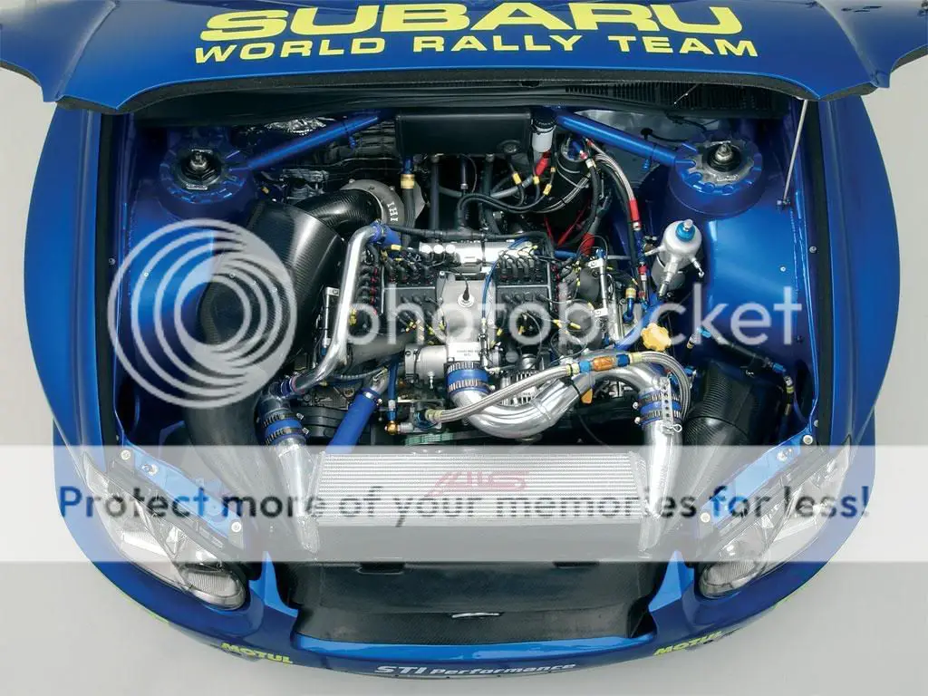
All that being said, it appears the large diameter pipe used on the Subaru cars is a result of the abnormally small intake plenum. The standard Subaru intake design has an interior volume which is almost exclusively runner rather than plenum. This larger pipe acts as a repository considering the space limitations above the motor. I have an STI Manifold in my garage and I can fill it to find it's actual volume and compare it to the 1G manifold I have.

Here is another way they have tried to increase that plenum size.

11bkq5y.jpg


I'll have to ask but it makes sense that at some point, the size of the plenum becomes negotiable, that is, in a race application on a forced induction motor, the plenum size needs to be bigger, but how much bigger is speculative. It appears in many of these Subaru configurations, they are simply going for as much volume as they can get within the limited space restrictions. I know during intake construction, there are many opinions on how much plenum volume is needed for a particular displacement motor. I would imagine more is better to a point in alot of applications, especially in high RPM racing applications. I don't think the specific size is as technical as the comparison to tuned headers however.

/brox
 
Support Vendors who Support the GVR-4 Community
Boosted Fabrication ECM Tuning ExtremePSI Fuel Injector Clinic Jacks Transmissions JNZ Tuning Kiggly Racing Morrison Fabrications RixRacing RockAuto RTM Racing STM Tuned
Top