Jon
Staff member
DISCONNECT YOUR VEHICLE'S BATTERY FIRST.

What you will need:
1)Phillips head screwdriver
2)Wire stripper/cutter (razor blade)
3)Soldering iron

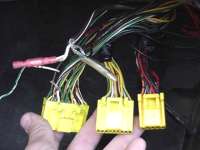
Unplugging the connectors to the ECU
1) Remove the passenger rocker panel cover and kick panel, and pull back the carpet. (for a DSM, the ECU is located behind the radio)
2) Unplug the connectors from the ECU behind the glovebox. (This will probably be easier if you open the glovebox past its catches)
NOTE: All wiring instructions are referrenced as looking directly at the yellow connectors.

Connecting the wires
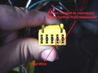
1) Power Wire: Connect the Red wire of the AFC harness to the Red wire with Black bands corresponding to the connector hole as shown above (bottom row, 2nd from right).
2) Ground Wire: 1: Connect the Brown wire of the AFC harness to the Black wire with Orange bands corresponding to the connector hole as shown above (bottom row, furthest on the right).
3) Ground Wire 2: Connect the Black wire of the AFC harness to the same Black wire with Orange bands as you did the Brown wire. Be sure to connect the Brown wire closer to the ECU/connector than the Black wire.
Failure to do so may result in improper product operation and engine damage.

Wiring the AFC into the 24 pin connector
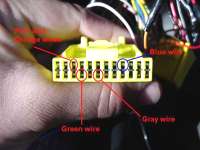
1) RPM Wire: Connect the Green wire of the AFC harness to the Black wire corresponding to the connector hole as shown above (bottom row, 4th from left).
2) Throttle Signal Wire: Connect the Gray wire of the AFC harness to the Green wire with a white stripe, corresponding to the connector hole as shown above (bottom row, 6th from left).
3) Air Flow Signal: Cut the Green wire with a blue stripe and Orange bands, corresponding to the connector hole as shown above (top row 3rd from left). This is the Air Flow signal wire. The AFC will intercept this wire and allow you to adjust the MAS signal to the ECU so leave enough wire from the connector so you can splice in.
4) AFC Connections: Connect the Orange wire (input to the AFC) of the AFC harness to the wire you cut from the 24 Pin connector. Connect the Pink wire (output from the AFC) of the AFC harness to the part of the wire still on the connector.
5) (OPTIONAL) Sensor 2 - Oxygen Sensor: Connect the Blue wire of the AFC harness to the White wire with Orange bands corresponding to the connector hole as shown above [blue circle] (top row, 4th connector from the right). This is the Oxygen sensor signal to the ECU. You can view this signal in the "etc." menu, under "Sensor chk".
6) Setup: Car Type is 4 cylinder and progressive throttle. Air flow type is Karman Vortex.
Written by JOHN LAMBERT

What you will need:
1)Phillips head screwdriver
2)Wire stripper/cutter (razor blade)
3)Soldering iron

Unplugging the connectors to the ECU
1) Remove the passenger rocker panel cover and kick panel, and pull back the carpet. (for a DSM, the ECU is located behind the radio)
2) Unplug the connectors from the ECU behind the glovebox. (This will probably be easier if you open the glovebox past its catches)
NOTE: All wiring instructions are referrenced as looking directly at the yellow connectors.

Connecting the wires
1) Power Wire: Connect the Red wire of the AFC harness to the Red wire with Black bands corresponding to the connector hole as shown above (bottom row, 2nd from right).
2) Ground Wire: 1: Connect the Brown wire of the AFC harness to the Black wire with Orange bands corresponding to the connector hole as shown above (bottom row, furthest on the right).
3) Ground Wire 2: Connect the Black wire of the AFC harness to the same Black wire with Orange bands as you did the Brown wire. Be sure to connect the Brown wire closer to the ECU/connector than the Black wire.
Failure to do so may result in improper product operation and engine damage.

Wiring the AFC into the 24 pin connector
1) RPM Wire: Connect the Green wire of the AFC harness to the Black wire corresponding to the connector hole as shown above (bottom row, 4th from left).
2) Throttle Signal Wire: Connect the Gray wire of the AFC harness to the Green wire with a white stripe, corresponding to the connector hole as shown above (bottom row, 6th from left).
3) Air Flow Signal: Cut the Green wire with a blue stripe and Orange bands, corresponding to the connector hole as shown above (top row 3rd from left). This is the Air Flow signal wire. The AFC will intercept this wire and allow you to adjust the MAS signal to the ECU so leave enough wire from the connector so you can splice in.
4) AFC Connections: Connect the Orange wire (input to the AFC) of the AFC harness to the wire you cut from the 24 Pin connector. Connect the Pink wire (output from the AFC) of the AFC harness to the part of the wire still on the connector.
5) (OPTIONAL) Sensor 2 - Oxygen Sensor: Connect the Blue wire of the AFC harness to the White wire with Orange bands corresponding to the connector hole as shown above [blue circle] (top row, 4th connector from the right). This is the Oxygen sensor signal to the ECU. You can view this signal in the "etc." menu, under "Sensor chk".
6) Setup: Car Type is 4 cylinder and progressive throttle. Air flow type is Karman Vortex.
Written by JOHN LAMBERT
Last edited by a moderator:


