The Top Mitsubishi Galant VR-4 Resource

Join the best E39A 1991-1992 Mitsubishi Galant VR-4 community and document your GVR4 journey.

  • Software Upgraded - Reset Your Password to Login
    In order to log in after the forum software change, you need to reset your password. If you don't have access to the email address you used to register your GVR4.org account, you won't be able to reset your password. In that case, follow the instructions here to regain access to the forum.

New to Mitsubishi...few GVR4 questions

Joined
Apr 2, 2020
Messages
24
Location
Tulsa, OK
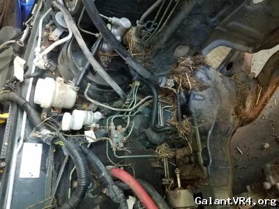
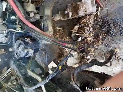
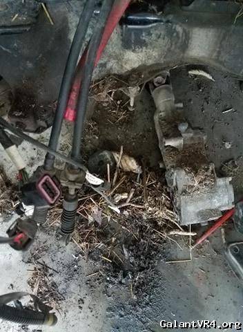
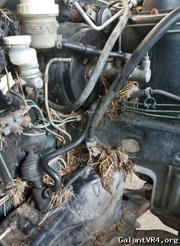
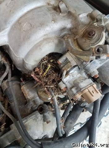
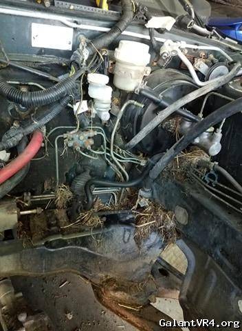
Ok, so the reason for the removal of the engine was to able to clean all of the rat nests out of the engine bay. I couldnt even see the subframes and since I dont know these motors....at all....I figured that I would just pull it and clean everything out so that I could get a good look at connections/electrical items that I may have looked over. I understand that this may have made it a bit more difficult to troubleshoot but I needed to be able to access things that I did not know were where.

The crap that are in these pictures are after I already removed pounds and pounds of crap and swept it out of the garage.


img.php


img.php


img.php

img.php
 
Joined
Apr 2, 2020
Messages
24
Location
Tulsa, OK
After speaking with Toybreaker and listening to his words, I started to check deeper into the wiring.

I started off by getting under the dash to check the connections on the fuse box down there. Wiring and connectors all seem unmolested and did not see any corrosion on the pins.


img.php

img.php


img.php


Joined
Apr 2, 2020
Messages
24
Location
Tulsa, OK
After looking at the connectors and pins on the underdash fuse box, I then pulled the ignition switch apart to get it out of the car to look at the contacts within:

This is what it looked like when I pulled it out, clean
img.php


Then I got the plastic cap off and the top copper plate fell out, I am pretty sure this is how it is supposed to sit
img.php


The lower copper plate
img.php


The springs
img.php


The pins in the connector, clean. the female connectors are just as clean
img.php


Should I clean this stuff off and add something new?
 
Joined
Apr 2, 2020
Messages
24
Location
Tulsa, OK
After looking at the ignition switch, I then looked at all of the wiring that I could see from the drivers floorboard and everything looked just as OEM as it should.

From there I went over to the passenger side and pulled the glovebox out to take a gander at everything behind that portion of the dash and nothing looked molested in any way. I peeked behind the center console and all wiring (that I could see) looked great.

I then pulled the ECU to look for popped caps:

looks as if it hasnt ever been touched. The screws didnt seem to have any bit marks on them either.


Connector pins looked great


Caps dont seem to be burst from the tops and even looking underneath, between the board and them, they dont seem to have burst


Nothing seems out of place/corroded on the backside either
 
Joined
Apr 2, 2020
Messages
24
Location
Tulsa, OK
After the ECU, I went to where the batter tray is and removed the "cold air" tube of the factory intake and I found some rat-ness


The little flat, black electronic is completely disconnected by chewed wires. The relay has knicks taken out of a few wires


This little piece is completely chewed through, turn signals?
 
Joined
Apr 2, 2020
Messages
24
Location
Tulsa, OK
Random other rat-ness

Connector that is on the harness that goes to the starter
img.php


Ground from the firewall to intake manifold. Completely chewed through
img.php


wire completely chewed through by the 3 things over on the drivers side. What are these?
img.php


Connector that plugs in by the throttle body, completely chewed through
img.php


Part on the back of the intake manifold, completely chewed through on both sides.
img.php
 

iceman69510

Turn Right Racing
Staff member
Joined
Mar 5, 2001
Messages
10,964
Location
Michigan
Alright, you have some work cut out for you. That little black rectangle is a multi-ground location. You definitely need to fix that and all the other grounds.

If you find you need connectors or pins to repair some of them, I have a fairly good selection of used/new connectors and some pins. Work your way through it all systematically. I/we on the board can help figure out if you have problems.

Taking the engine out looks like a reasonable move given the rat nests and the discoveries.
 

toybreaker

iconoclast
Joined
Apr 30, 2006
Messages
3,581
Thanks for the pics, that helps us see what you're dealing with!


Quoting BlackHornet:

Should I clean this stuff off and add something new?


That's a special kind of grease, so I'm not sure what to tell you there.

Part di-electric, part actual lubricant for the contacts, it's an engineered product specifically for that type of an application.

If it's not dirty, I'd try and salvage what's there and redistribute it to where it's needed.


Ignition switch actually looked pretty good inside.

No corrosion and the contacts didn't appear to be burned or damaged, so the problems probably lie elsewhere

It's always best to check switches under load, as testing for resistance in the different switch positions with an ohmmeter can give confusing results. The switch is designed to carry large loads, and the small amount of current from an ohmmeter won't always conduct well enough thru grease/corrosion/scmutz on the contacts well enough to give an accurate read on the functionality of the switch.


I think a systematic approach will give the best results to troubleshoot this problem.

Start with a complete visual inspection of all the harness runs, making note of any damaged areas.

It does look like several of the grounds have been compromised on the r/f fenderwell, as well as up on the firewall.

I would continue to try and run down all the individual branches of the harness and visually inspect the entire thing. I've seen issues where it runs inside that r/f fenderwell. You'll have to remove the innerfenderliner to see that run, but it's quite possible that got chewed on where it joins the firewall/cowl area.


Quoting BlackHornet:
wire completely chewed through by the 3 things over on the drivers side. What are these?
img.php


The good news is they started your abs removal, so you got that going for you. /ubbthreads/images/graemlins/grin.gif


Can you get a better picture of the ecu?

Try and get a good shot of the caps, please, as it looks like it needs some love.

Thanks!
 
Joined
Apr 2, 2020
Messages
24
Location
Tulsa, OK
I pulled the Right-front Inner fenderwell liner and the only wire that I saw was the ABS wire coming into the wheel well and then looping down to the strut. I will look again to confirm 100%.

Here are some pictures of the caps:

With Flash


Without Flash


The circled solder points are the caps. I do not see any cracks in the solder joints. There are a few joints that have a "muck" on them but its the same stuff that is brown on the ecu connector pinout shroud.


toybreaker

iconoclast
Joined
Apr 30, 2006
Messages
3,581
Quoting toybreaker:
I would continue to try and run down all the individual branches of the harness and visually inspect the entire thing. I've seen issues where it runs inside that r/f fenderwell. You'll have to remove the innerfenderliner to see that run, but it's quite possible that got chewed on where it joins the firewall/cowl area.


Quoting BlackHornet:
I pulled the Right-front Inner fenderwell liner and the only wire that I saw was the ABS wire coming into the wheel well and then looping down to the strut. I will look again to confirm 100%.


my most humble apologies!

... it's been awhile since I had to look at a vr4 harness.

The harness I wanted you to look at actually goes forward (from the fusebox on the r/f by the batttery) then down the radiator support, across the bottom and then up the drivers side radiator support, and then behind the headlight.

It then pops thru an opening in the left fenderwell to the otherside and runs across the top of the outerfenderwell under the splashshield and back to the firewall.

I've seen rodents do a number on that harness at the rubber grommet on the firewall.

That harness has almost everything important in it, so it's good to inspect every inch of the entire run.

... good thing you pulled the motor /ubbthreads/images/graemlins/grin.gif

[edit]
Can someone else make the call on the ecu?

Those look like the original caps, and there's a spoogy looking smudge looking appearance on one of the surface mount components by the cap

... but I can't see for sh*t anymore, so maybe it's just shadows /ubbthreads/images/graemlins/dunno.gif
 
Last edited:
Joined
Apr 2, 2020
Messages
24
Location
Tulsa, OK
Quote:
The harness I wanted you to look at actually goes forward (from the fusebox on the r/f by the batttery) then down the radiator support, across the bottom and then up the drivers side radiator support, and then behind the headlight.

It then pops thru an opening in the left fenderwell to the otherside and runs across the top of the outerfenderwell under the splashshield and back to the firewall.


Will do this tomorrow and report back.

We were under Tornado Watch all day here and so I wasnt able to get out to the garage because of the weather and so I fiddled with the ignition switch. I smeared the current "grease" that was on the copper plates and cleaned up the copper contacts. I then pulled the multimeter back out of the box ONLY to test continuity of the ignition contacts. I then made notes of what was making signal:


All seems to be good there and making contact easily.

I then pulled the actual keyed portion out of the slot and all looks well. Could maybe use some lube but I dont want to risk pulled the snap ring off and having the internals fall apart.
 

toybreaker

iconoclast
Joined
Apr 30, 2006
Messages
3,581
The good news is the interior stuff looked pretty mint and unmolested.

I think once you identify all the damaged areas and repair them, things will be golden.
 
Joined
Apr 2, 2020
Messages
24
Location
Tulsa, OK
Ok, had a bit of a break and went out into the garage. The harness does, in fact, go inside of the left front quarter panel. I pulled the liner on that side of the harness doesnt look like any rodents ventured there.

Tracing the harness:
So, starting back over by the battery. I traced the harness down the rad support and across the bottom, then back up the other side.

The harness leg that goes towards the Alternator, a little wire was chewed in half.


Then, at the actual Alternator connector, this wire came from somewhere.


Then continuing on, the two little wires that are going to the AC sensor had some bite marks.


I did see some up by the ABS block. These wires dont seem to be chewed through the actual insulation, but moreso the sheathing. This is the ABS harness side of the connectors and not the actual car harness.


These marks are under the 3 connectors on top of the ABS box. That is the actual car harness.


More sheathing missing on the ABS box side of things. Wire insulation does not appear to be gotten to.


I then followed the main harness through the fender and saw nothing. The harness then splits; one leg goes back to the engine bay for a relay and the horn and the other leg continues on into the car for the underdash fuse block. Nothing seemed to be tampered with on these two legs.

I then had part of the other side of the engine bays harness sitting on the windshield from when I pulled the engine. This is the harness that splits down the AC Compressor, this has some rat-ness.


This is the junction where the harness splits into the injector harness and the AC Compressor harness. I do not see any bare wires here.


Then up to the injectors.....this is pretty self explanatory.


mk2davis

Well-known member
Joined
Mar 1, 2015
Messages
191
Location
Ventura, CA
2 suggestions that may help. It looks like your car is going to be down a while. You might want to send your ECU to ecmtuning and have it looked at and your eprom socketed if you are considering ecmlink. It's not expensive (60 bucks iirc), and it's nice to know any future issues aren't ECU based. My other suggestion is to find a fsm. There's one in the archives, but I found a more detailed one after a search. If you can't find it, let me know and I'll try and post mine in Dropbox and send you a link. It looks like the wiring diagrams could be of use to you.
 
Joined
Apr 2, 2020
Messages
24
Location
Tulsa, OK
Quote:
2 suggestions that may help. It looks like your car is going to be down a while. You might want to send your ECU to ecmtuning and have it looked at and your eprom socketed if you are considering ecmlink. It's not expensive (60 bucks iirc), and it's nice to know any future issues aren't ECU based. My other suggestion is to find a fsm. There's one in the archives, but I found a more detailed one after a search. If you can't find it, let me know and I'll try and post mine in Dropbox and send you a link. It looks like the wiring diagrams could be of use to you.


I will most likely be doing ECMlink at some point and so I have considered sending the ECU to them to check out and get ready for it but Im throttling the amount of actual money that I am putting into this until I get the title into my name. Oklahoma has a different process than what I am used to in Texas and so its a waiting game on getting that done. But yes, solid suggestion, and will most likely be doing that in the future.

I did find the FSMs in the archives here but seemed to have a hard time finding certain areas that I was wanting to look at.
 

mk2davis

Well-known member
Joined
Mar 1, 2015
Messages
191
Location
Ventura, CA
Hopefully this will help. I think you'll use the 6 Bolt electrical, but help yourself to it all. click
 
Joined
Apr 2, 2020
Messages
24
Location
Tulsa, OK
Ok guys,

Ive been looking more at the harness for rodent marks and I THINK that I have spotted all...so far. My next task is to check the wiring back at the fuel pump and tail lights. I was going to go ahead and order some wire splices and I have been doing research for what to use. I would like to keep the splice small and so I do not want large insulated butt connectors within the loom. In the past, I have used butt connectors that I have stripped the plastic from and crimped the metal barrel and then used marine heat shrink over that, this was to keep the wire as thin as possible.

The other way that I have done was to strip back wire on each side and wrap it around each other to form a "knot" and then I can fill that knot with solder and marine heat shrink it. Like:


However, I have been researching other options out there and have come up with:


img.php

to form


then use a double crimp, solder into it, then marine heat shrink over it. Mechanical hold and then the solder hold.

I have a decent crimping tool that will do double crimps as well as the solder and marine heat shrink.


If anybody has any other recommendations, please share! I would like to get some wire stuff on order and shipping this direction because this COVID stuff here seems to have slowed down shipping a little.
 

iceman69510

Turn Right Racing
Staff member
Joined
Mar 5, 2001
Messages
10,964
Location
Michigan
In the automotive world, mechanical crimps are the norm, especially with connectors. Now splice or Y-joints are often soldered, but not recommended everywhere. Soldering wicks into wires and destroys the inherent flexibility in the multi-strand wiring. I would suggest just using the mechanical crimps. Properly applied they should need no solder. Again, especially important in location where flexibility is important.

Those joints look not too bad for connecting 2 wires to 1. I have not used them myself. I typically used uninsulated butt connectors and heat shrink over them to keep diameter small. That is sometimes not so feasible for 2-1 connections though.
 
Support Vendors who Support the GVR-4 Community
Boosted Fabrication ECM Tuning ExtremePSI Fuel Injector Clinic Jacks Transmissions JNZ Tuning Kiggly Racing Morrison Fabrications RixRacing RockAuto RTM Racing STM Tuned
Top