The Top Mitsubishi Galant VR-4 Resource

Join the best E39A 1991-1992 Mitsubishi Galant VR-4 community and document your GVR4 journey. Login to browse without most ads.

MAS CEL: Sensors Ground Pins 17&24

donkeylips

Well-known member
Joined
Jun 18, 2009
Messages
552
Location
Rochester, NY
The previous owner of my car may have hacked the engine bay wiring harness a bit, since I've had a CEL for the MAS ever since I put the car together. I checked continuity between the pins on the MAS and their corresponding pins on the ECU connectors. I checked this on 924/1000 and 108/1000 and compared the results.

Everything checks out except for pin 6 on the MAS - which should go to pins 17 and 24 - Sensors Ground.

I think there should also be continuity between 17 and 24, but I don't have it. Does anybody know where in the harness that these wires are supposed to connect? They just seem to go from the ECU up into the harness. I haven't seen anything obviously out of place. I'm not great with wiring diagrams, and I'm not sure where to go from here.

Thanks!
 

donkeylips

Well-known member
Joined
Jun 18, 2009
Messages
552
Location
Rochester, NY
Actually I mentioned that it's pin 6 on the MAS (from my '91 Talon FSM) but it looks like it's pin 4 in my Galant manual. Not sure why, because it's pin 6 on my Galant that's actually right. It's not really relevant to the problem at hand though.
 

strokin4dr

Well-known member
Joined
Aug 30, 2005
Messages
2,770
Location
Savannah, GA
I'm not positive on where the grounding points are, but check the ground wires on the terminal that bolt to the ecu case.
 

donkeylips

Well-known member
Joined
Jun 18, 2009
Messages
552
Location
Rochester, NY
That was one of my first thoughts but after looking into it a bit more, I don't think it would affect my not having continuity between any of the three pins.
 

broxma

Well-known member
Joined
Nov 16, 2009
Messages
911
Location
San Antonio Tx
The sensor ground is 24. Check continuity between 24 and 101 and 106. Those are the Chassis grounds. Also, since you're down there, check 24 to the ground on the kick panel and from there to the sensor connector. That spot on the kick panel (Ground point #7) is actually where all sensors get their ground from. I do not show anything at pin 7.
 

donkeylips

Well-known member
Joined
Jun 18, 2009
Messages
552
Location
Rochester, NY
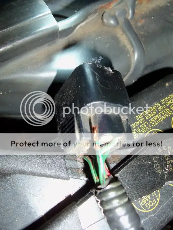
Hey Broxma...it's YOUR fault!! You had to go and be a nice guy and send me a MAS pigtail for the cost of shipping...
100_1189.jpg


Is there an easy way to fix this without getting a new connector?


It turns out that I was wrong, and that I DID have continuity between pins 24 and 17. I figured this out after checking my coolant temp sensor and it was fine. So it looks like it's all figured out, I just need to figure out if I can save the connector.
 

strokin4dr

Well-known member
Joined
Aug 30, 2005
Messages
2,770
Location
Savannah, GA
You can pull a pin with some wire attached from another connector, spice it to the broken wire, remove old pin and then reinstall. No need for another connector.
 

broxma

Well-known member
Joined
Nov 16, 2009
Messages
911
Location
San Antonio Tx
Or I can send you another connector. Is it my fault you rough housed the thing into submission? It was free. Gimme a break.

I can send you another. I am going to the yard tomorrow. Hell, I'll grab two.

/brox
 

donkeylips

Well-known member
Joined
Jun 18, 2009
Messages
552
Location
Rochester, NY
Quoting strokin4dr:
You can pull a pin with some wire attached from another connector, spice it to the broken wire, remove old pin and then reinstall. No need for another connector.


How exactly do I go about removing the old pins?


And Brox, don't worry about it! But if you happen to get your hands on another spare, I wouldn't mind getting another one for the cost of shipping. Only if you feel like it though, it's not a big deal.
 

strokin4dr

Well-known member
Joined
Aug 30, 2005
Messages
2,770
Location
Savannah, GA
Use a pick or a small (jeweler's size) flat head to remove the plastic cap on the end of the harness plug. Once this is removed, look into the front of the plug at the pin you want to remove. On one side of the pin there will be a plastic tab. Can be hard to see at first if you have never done it before. This tab needs to be bent away from the pin and then the pin pulled out the back by the wire. In your case with no wire connected you will have to pry the tab back while simultaneously pushing the pin out with another small tool from the front. Its very easy once you get the hang of it. Good luck!
-Ryan
 

broxma

Well-known member
Joined
Nov 16, 2009
Messages
911
Location
San Antonio Tx
Picked one up today for you actually. Steve has it. I'll get it from him and send it out. Send me your address again.

/brox
 

donkeylips

Well-known member
Joined
Jun 18, 2009
Messages
552
Location
Rochester, NY
Quoting strokin4dr:
Use a pick or a small (jeweler's size) flat head to remove the plastic cap on the end of the harness plug. Once this is removed, look into the front of the plug at the pin you want to remove. On one side of the pin there will be a plastic tab. Can be hard to see at first if you have never done it before. This tab needs to be bent away from the pin and then the pin pulled out the back by the wire. In your case with no wire connected you will have to pry the tab back while simultaneously pushing the pin out with another small tool from the front. Its very easy once you get the hang of it. Good luck!
-Ryan


I'm pretty sure I found the plastic tab, but I couldn't get the thing out. Trying to push it I think I mangled the pin a bit. Oh well, maybe I'll figure it out in the future.
 
Support Vendors who Support the GVR-4 Community
Boosted Fabrication ECM Tuning ExtremePSI Fuel Injector Clinic Jacks Transmissions JNZ Tuning Kiggly Racing Morrison Fabrications RixRacing RockAuto RTM Racing STM Tuned

Recent Forum Posts

Top