GolfBall
Well-known member
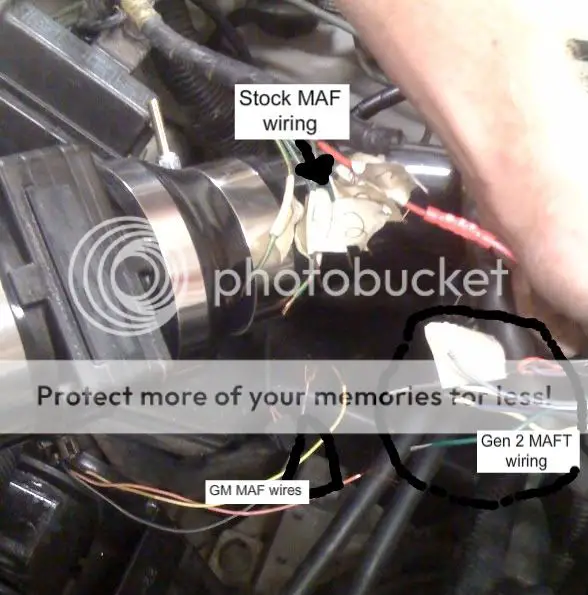
so im working on gettin my vr4 running and am to the point where i need to wire up the Gen 2 MAFT to a 3" gm maf....
this is where im at....
been searching and reading everywhere and cant find anything helpfull.... the combo of being a 1g vr4 with dsm-link and Gen 2 just isn't that popular i guess....
this is where im at....
been searching and reading everywhere and cant find anything helpfull.... the combo of being a 1g vr4 with dsm-link and Gen 2 just isn't that popular i guess....
