misterfixit
Well-known member
Hi I was posting with a kinda specific request. I have just gotten my EEprom ecu finally, and as I was not ruushed to get it into the car I wanted to get a project underway I've been mulling over for some while and hopefully give something back to the community.
Lots of people have big involvement in the ecu's and I make no gains about being a program whizz, but as I have some patience and an ecu at my disposal I pulled it down somewhat as I was changing the caps and socketing it.
My goal is to produce a wiring diagram for the ecu, as i think it would be a useful contribution as I don't know of one that exisits yet.

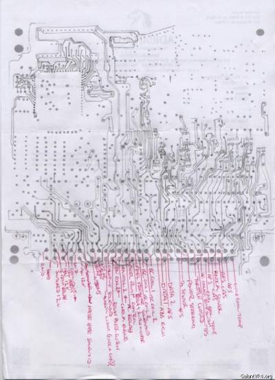
Here is the progress so far on the front side of the board.

The reason I'm posting is I was hoping someone, or maybe a few people could fill in the gaps. If there are any dead ecus on shelve (unrepairable preferrably) that the microcontroller and the other chips I couldn't see under could be pulled off, I'm kinda asking for some good high resoloution pics of what goes on underneath and the knock board which would be fantastic. Otherwise I'll have to wait and bell the rest of the board with my meter.
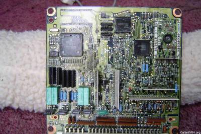
The white residue on the board is the conformal coating which can be washed off with contact cleaner!
The board numbber, as seen on the upper pic is e331b989d, this board is also used in us turbo and non turbo ecu's.
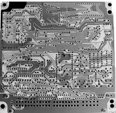
Here's the underside,

Once I have the rest of the upper side I can overlay the underside and start creating a schematic.
I hope you guys can help, and I hope when complete this helps.
Rich
Lots of people have big involvement in the ecu's and I make no gains about being a program whizz, but as I have some patience and an ecu at my disposal I pulled it down somewhat as I was changing the caps and socketing it.
My goal is to produce a wiring diagram for the ecu, as i think it would be a useful contribution as I don't know of one that exisits yet.
Here is the progress so far on the front side of the board.
The reason I'm posting is I was hoping someone, or maybe a few people could fill in the gaps. If there are any dead ecus on shelve (unrepairable preferrably) that the microcontroller and the other chips I couldn't see under could be pulled off, I'm kinda asking for some good high resoloution pics of what goes on underneath and the knock board which would be fantastic. Otherwise I'll have to wait and bell the rest of the board with my meter.
The white residue on the board is the conformal coating which can be washed off with contact cleaner!
The board numbber, as seen on the upper pic is e331b989d, this board is also used in us turbo and non turbo ecu's.
Here's the underside,
Once I have the rest of the upper side I can overlay the underside and start creating a schematic.
I hope you guys can help, and I hope when complete this helps.
Rich


