The Top Mitsubishi Galant VR-4 Resource

Join the best E39A 1991-1992 Mitsubishi Galant VR-4 community and document your GVR4 journey.

  • Software Upgraded - Reset Your Password to Login
    In order to log in after the forum software change, you need to reset your password. If you don't have access to the email address you used to register your GVR4.org account, you won't be able to reset your password. In that case, follow the instructions here to regain access to the forum.

ECU Coolant Temp Sens Location and Vacuum routing clarification.

Tisquantum

Active member
Joined
Sep 20, 2015
Messages
25
Location
Northern Willamette Valley, OR
6 incorrect ECU pins fixed later and I finally got to drive her for the first time. ECMLink was logging realistic look coolant temps, how ever I noticed my dash coolant temp gauge was not reading. As I was inspecting things further I discovered that the ECU is getting it's coolant temp from the radiator, if I am not mistaken. This seems like all sort of wrong. Since I am in the process of pulling the whole of the wiring from the car, stripping the now unnecessary portions (ABS, A/C, Factory Stereo amp, etc.) should I just tap the factory location and install a GM sensor and wire it back as such or is there some benefit to having the sensor in the radiator?

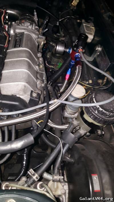
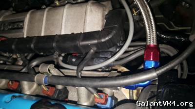
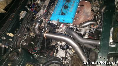
I purchased a used AEM Tru Boost as well as tial Q BOV. I have read on this one for 4 hours and can't find any information on the BEST solution, just what the options are. I attached a few pictures that show the routing of the vacuum/pressure lines. What is the MOST ideal routing/sources for vac/pressure? I am pretty sure at this point I am either going to drill and tap my compressor housing or my J-pipe for the Tru Boost solenoid, get my BOV from the stock location on the front underside(closer to the head, not the firewall) and the pressure for the gauge in the car from P on the throttle body. I also see that the guys who installed this for me have it configured for an external waste gate, which must not be as effective as having it setup for my internal waste gate. The BOV currently is getting it's /vac/press from the stock location, teed to the tru boost. Leaving my FPR to get it's vac from the stock location as well.

What say you?


transparentdsm

Well-known member
Joined
Jul 27, 2011
Messages
3,690
Location
Cherry Hill, NJ
sensor in rad turns the fans, there are 3 sensors under the thermostat housing the two in the front are for the ECU and the dash. 2 pin is ecu single is dash.

this is just my opinion, but you shouldn't T things off of each other for boost sources. the FPR should def not have any sort or a T in it. i would recommend spending 15$ and getting a vacuum distribution block. its what i used for a while till i got around to tapping ports into my intake manifold.
 

GSTwithPSI

Well-known member
Joined
Jan 1, 2012
Messages
3,461
Location
SoCal
Regarding the ECU seeing coolant temp, you just need to verify the ECU is seeing a varied voltage from the coolant temp sensor (CTS). To do this, you can check for continuity between the CTS and ECU pin 20. All the information you need to do that is below.

The sensor for the gauge in the cluster is located in the front of the T-stat housing labed #1 in the diagram below. It's a single pin/wire.
img.php


Quoting GSTwithPSI:
The problem with the harness right there is somebody at Mitsubishi thought it would be a great idea to use duplicate colored wires. As a result, you have 6 wires total:

2 Green w/ black tracer
2 Yellow w/ green tracer
1 Blue w/ black tracer
1 Green w/ red tracer

The only way to decipher which green w/ black tracer and yellow w/ green tracer go the the CTS after the plugs have been cut of is to trace the harness back to the ECU.

1.) Green w/ black tracer = Front of T-stat housing T-pin of coolant temp sensor (crossbar of T)
2.) Green w/ black tracer = Top of T-stat housing two pin temp sensor for a/c cut out
3.) Yellow w/ green tracer = Front of T-stat housing T-pin of coolant temp sensor (stem of T position)
4.) Yellow w/ green tracer = Front of T-stat housing single pin for coolant temp gauge
5.) Blue w/ black tracer = Single pin coolant temp sensor for A/C on rear T-stat housing
6.) Green w/ red tracer = Top of T-stat housing Two pin temp sensor for a/c cut out


From another related thread:
Quoting GSTwithPSI:
You need a DVOM with long leads. I put my meter on the windshield of the car, and clamp one lead on the wire at the sensor connector. Then, I take the other lead and probe the ECU pin while looking at the meter through the windshield.

Coolant temp sensor wiring:
T-pin front: Coolant temp sensor (connector B02): Green/black (crossbar of T) and yellow/green (stem of T position)

First, clamp a meter lead on the Green/black (crossbar of T, or top part of the T) wire at the sensor.

Then, you need to find pin 20 at the ECU: ECU Pinout. Put your meter lead there, and see if there is continuity between the ECU pin, and the sensor connector. If not, then your ECU is not getting a signal from your coolant temp sensor. And, I'd bet my life that it isn't getting one.

The other wire, yellow/green (stem of T position) goes to ground. It goes to the ECU sensors ground on pin 24. You can do the same thing for this circuit as you did for the other, or you could just ground it somewhere in the engine compartment. Eventually, you want to make sure it is properly grounded through the engine harness back to the ECU though.

If your car isn't seeing coolant temperature, it is screwing all kinds of sh*t up. You need to verify it is working. It would be best if you had a logger or something, that way you could hook it up and see exactly what the ECU is seeing...

Lastly, here is a link to the library where the coolant sensor wiring diagram is located. click Look on page 148 (actual document page number, not the Adobe page number)


Threads: click and click and click


For the vacuum routing, use the stock location for the BOV. For the other components requiring vacuum, use whatever nipples are left on the manifold, or use a vacuum distribution block as Shane suggested.

You should have saved your money on the AEM Tru Boost. ECMlink has a far more robust option for controlling boost, which can be implemented for a fraction of the cost. You should consider ditching the AEM, and using ECMlink for electronic boost control. See here for how to do that: click
 
Last edited:

Tisquantum

Active member
Joined
Sep 20, 2015
Messages
25
Location
Northern Willamette Valley, OR
When using ECMLink to control boost as shown in the link above, will it be necessary for me to tap a nipple onto my intake tube just behind the filter as I have no MAF and am running SD?
 

Tisquantum

Active member
Joined
Sep 20, 2015
Messages
25
Location
Northern Willamette Valley, OR
Thank you a ton kind sir! I am taking my J-pipe, my (custom SS) throttle body elbow and my IC outlet pipe to my welder tomorrow to get the bungs welded on. The IC outlet pipe bung will initially be plugged and sealed, it is for my water/meth injection system.

Any recommendations on where I might get a stock BCS? I am toying with buying the basic Ingersol-Rand that DSMGraveyard says ECMlink recommends for boost control.
 

GSTwithPSI

Well-known member
Joined
Jan 1, 2012
Messages
3,461
Location
SoCal
You should have just used the stock one that's free. I'm sure someone here has one laying around. If not, this guy will hook you up: click . The stock BCS plugs directly into the factory harness, and works just as well.
 
Last edited:

Tisquantum

Active member
Joined
Sep 20, 2015
Messages
25
Location
Northern Willamette Valley, OR
I bought the car with a hardware store style boost regulator, I don't think the factory plug for he BCS is even on the harness at this point. On the off chance that I did get the stock BCS with the car, the shop who had my car must have taken it, along with a fair amount of other parts...

The BCS from ECMLink will be here in a few days.

On a different note: yesterday my FP intake pipe arrived. I got that sh*t ready to put on the car so fast your head would have spun, only to find that my upper IC pipe is just about as wrong as one could be. Luckily I had already arranged to have my welder friend at a few bungs for my IAT and one on my J pipe for boost pressure, so we will hack it apart and get it all straight this weekend.
 

GSTwithPSI

Well-known member
Joined
Jan 1, 2012
Messages
3,461
Location
SoCal
Well, that sucks, because you're still going to need the factory BCS wiring to control the IR solenoid you bought. So, hopefully he didn't cut it off completely.
 

Tisquantum

Active member
Joined
Sep 20, 2015
Messages
25
Location
Northern Willamette Valley, OR
While it is unfortunate I paid to move backwards with the car, this was the last straw with the wiring harness. So I am going to follow your lead and remove and repair/replace/remove as needed. Today I will get the remainder of the ABS harness out, order some proper jackets for the engine bay harness and the Sheridan connector kit.

This community is great. Thank you all!
 
Support Vendors who Support the GVR-4 Community
Boosted Fabrication ECM Tuning ExtremePSI Fuel Injector Clinic Jacks Transmissions JNZ Tuning Kiggly Racing Morrison Fabrications RixRacing RockAuto RTM Racing STM Tuned
Top