The Top Mitsubishi Galant VR-4 Resource

Join the best E39A 1991-1992 Mitsubishi Galant VR-4 community and document your GVR4 journey.

  • Software Upgraded - Reset Your Password to Login
    In order to log in after the forum software change, you need to reset your password. If you don't have access to the email address you used to register your GVR4.org account, you won't be able to reset your password. In that case, follow the instructions here to regain access to the forum.

Cyclone Manifold Coils Transistors Installation How To - Bias to '89 Mirage/Colt

FlyingEagle

Staff member
Joined
Mar 5, 2005
Messages
1,635
Location
THE Ottawa
I have a 1989 Colt (Mirage) turbo. 90 DSM style electronics (90 Eprom ECU, coil packs, transistors, tach noise filter on plenum corner) are used from what I know.

If this can be made into a simple how-to for people, it would be great. I've had all these parts lying around since about 2008. /ubbthreads/images/graemlins/uhh.gif

More to follow, as I upload pics.
 
Last edited:

tektic

Well-known member
Joined
Dec 19, 2012
Messages
1,497
Location
ronkonkoma, ny
It depends on which ecu you will use. If your using a 90 coil pack and a 91+ ecu even after switching pin 14 your tachometer will bounce all over the place.

If you can, wire everything to 91 spec with 91 parts. If that's too much trouble, keydiver use to sell a tach signal adapter for the ecu swap. I don't know if there still available.

If you can live without a tach or get an aftermarket tach then it doesn't matter i guess.
 

FlyingEagle

Staff member
Joined
Mar 5, 2005
Messages
1,635
Location
THE Ottawa
^^^ I've seriously edited the first post, so the second post above will likely not make sense. Sorry about that tek.

I'll add this to the original post, but I will be using a 1990 DSM ECU, Federal. It's the same in all regards as an '89 Mirage turbo ECU, including pin-outs, and Eprom. ECU is chipped. I say it is the same, only because this is an Eprom unit, so it can be tweaked for injector size, and all the base variables that can be changed/manipulated. Just plugging in a non-Eprom 1.6L ECU into a 2.0L without changing the MAF/injectors, etc, would cause an issue yes. Just showing that most late 88/89/90 stuff with Eprom can be used in place of one another. Single board ECU's only!

I should probably do this:

Drill Transistor mount plate/tap for 90 style transistor mount holes x2.
Move wiring for transistor from timing cover upper location, so it's middle/top of the intake plenum.
Install wiring from 89 Coil packs with Tacho module.
This relieves the issue of adding a wire to the harness connector. The Tacho Filter adds a yellow wire, meaning 4 wires at the connector. Likely all 91 USDM DSM's and 91/92 USDM GVR's only have the three wire connections. 89 4g61t and 90 4g63t use 4 wires at the connector.
Extend wires at the Tacho module, or drill two new holes closer to the coil studs for the spade connectors, so the Tacho module can be mounted with no wiring modifications.
The black capacitor will also fit nicely near where the spark plug wires install to the towers.
That's a 5 minute nut/bolt swap + some drilling/tapping x4 holes. BAM!

Moment of clarity. Finally.

Pics to follow.

Cyclone coil packs and Power Transistor arrangement per ASA Japan.


Coil pack comparison: USDM 89 Colt/Mirage 4G61T with Tach Adapter for proper tachometer operation (90 DSM essentially) versus 90/91+ JDM Cyclone/ECI Multi Dual runner
Side by side --> JDM left - USDM right
Notice the small plate area with two screw holes, already tapped and ready to accept a Tacho Interface module .... surprise, surprise! Different era clusters getting that same bracket. I figured this out late in the evening, while wondering where to place the tacho interface. I mounted the tacho interface to this plate, but wires whether in original orientation to the coil studs, would not work, nor would they work with the wires switched at the tacho "IN" terminals (there are two terminals), and switched at the studs.
Solution : extend wires - which I am not a fan of doing, or drill two holes in the base plate, on the lip that comes up from where the coils mount, and directly centered below the two coils. I'll post pics when I can get that drilled and tapped to accept the stock screws.


Cyclone dual runner


Cyclone dual runner - harness plug 3 wire


Cyclone dual runner - wire shot with covers removed


USDM 4g61t - wire shot with covers removed


USDM 4g61t left(small bracket is welded in place (factory mod) to hold the Tach adapter) versus 90 DSM 4g63t. Also to note is a 4 wire connector on the left, 3 wire on the right.


Bottom view JDM left, USDM right
 
Last edited:

FlyingEagle

Staff member
Joined
Mar 5, 2005
Messages
1,635
Location
THE Ottawa
Got my brackets cleaned, rust prepped and painted. Curing overnight before re-assembly tomorrow.
Cyclone Transistor plate now drilled and tapped to accept the 90 style transistor. Holes for the 90 style tach module get drilled tomorrow.
So far so good.
 

tektic

Well-known member
Joined
Dec 19, 2012
Messages
1,497
Location
ronkonkoma, ny
I have a cyclone coming in the mail. I think I'm going to have to fab these brackets. If you would, please post a picture of the brackets by them selves.

thanks
 

FlyingEagle

Staff member
Joined
Mar 5, 2005
Messages
1,635
Location
THE Ottawa
Server is having troubles tonight. Got pics with my good camera, including the cyclone transistor bracket, with ruler for dimensions.
Final pics of the coil packs with wiring now installed properly, and tacho module screwed down nicely to the coil bracket assembly.
I hope it fits. I just have to poke my head into the garage, but I'll do that when I have uploaded the pics.
 

FlyingEagle

Staff member
Joined
Mar 5, 2005
Messages
1,635
Location
THE Ottawa
Dual runner transistor plate and transistor appears to be 91 USDM style.


Plate drilled to accept 89 Colt/Mirage 4g61t/90 DSM style transistor


89 4g61t/90 style transistor with original plate


Newly drilled holes at base, allow tacho interface to be installed in close proximity to coil packs. If you want to lengthen your wires, you can use the original location that the tacho interface would have been installed on the side plate. Holes are already drilled, but the wiring on these models wasn't meant for this plate, so it was modified to work.


The 4 wire connector does slide right onto the mount rail beside the black box labelled, "250-0.47"
 

FlyingEagle

Staff member
Joined
Mar 5, 2005
Messages
1,635
Location
THE Ottawa
CREDIT DUE for some photos related to this HOW TO ARCHIVE thread:
click

Well, the coil packs go on today. I'll post back about that soon.
Last night I modified a few things to fit the Cyclone support bracket into my engine bay.

Here is a basic rundown of everything you need to see for tracing out vacuum lines on the cyclone setup.

Further cutting to the support was required due to contact on one small bolt head at the compressor housing. I likely cut out a little more than is required, but nothing is moving on the back side of the motor. Not compromising structure, but it will be painted to keep it from rusting.

This will be like a color coded, adult required for assembly, kids play toy. The vacuum lines are color coded, making their installation pretty easy with the correct diagram.

You will see color dots on the sensors - likely only original Mitsubishi sourced sensors are color coded this way, but now you know the solenoids to look out for, or that can be matched to look original/work the same way. The color dots match the color code hash marks on the vacuum lines!!!! :p
One vacuum line or two do not have color codes on them.

More of Cheekychimps Cyclone manifold views and diagrams via Misterfixit:


Last edited:

EHmotorsports

Well-known member
Joined
Sep 25, 2012
Messages
1,278
Location
Beaverton
On my build thead I show a couple pick of how I made a simple bracket using dsm coils for a cyclone manifold. May help with ideas for others. If you want I will post them with your approval:)

null-40.jpg


Original DSM coil bracket. The mounting tabs were removed and peeped for welding to the new bracket.
null-41.jpg

null-42.jpg

null-43.jpg

null-46.jpg

null-45.jpg
 
Last edited:

FlyingEagle

Staff member
Joined
Mar 5, 2005
Messages
1,635
Location
THE Ottawa
Any additional information welcomed.

For reference, the stock 1989 Mirage Colt turbo/NA, 1990 USDM and the Cyclone ECI Multi ('91 style wiring) coil packs (without brackets), ARE THE SAME COILS PACKS. Part numbers match, serial numbers obviously don't come in to play in this regard.

All three models we are comparing have differing brackets for the coils. 1989 Mirage has an extra bracket welded in place to accommodate the Tachometer Interface module, but is otherwise identical to the 1990 and 1991/94 coil mount brackets. Cyclone bracket is entirely different because it mounts to the drivers side of the Cyclone manifold, versus the 1990-94 coils which are nestled inside the U-shape of the USDM 1G intake manifold.

If people do not have a Cyclone coil mount, this is where a custom made piece would come in handy.

Fire away EHMotorsports!
 

FlyingEagle

Staff member
Joined
Mar 5, 2005
Messages
1,635
Location
THE Ottawa
BIG update:

Using NGK Blues for plug wires, you do not need longer spark plug wires unless you wish to preserve the original coil pack wiring orientation and subsequent swap of the coil wiring and plug wires to suit this.
I shall elaborate.

NGK Blue 7mm wires that are probably the most common standard wire for our 4G6X engines will not fit, lengthwise in their labelled positions or otherwise, when using the Cyclone manifold, original Cyclone coil pack location and standard spark plug wire bracketry located in the spark plug/head cover area. SOLUTION! You can manipulate the system.

I now have the pictures to show what you need to do, saving much time and headache for someone wanting to jump right into this installation scenario.

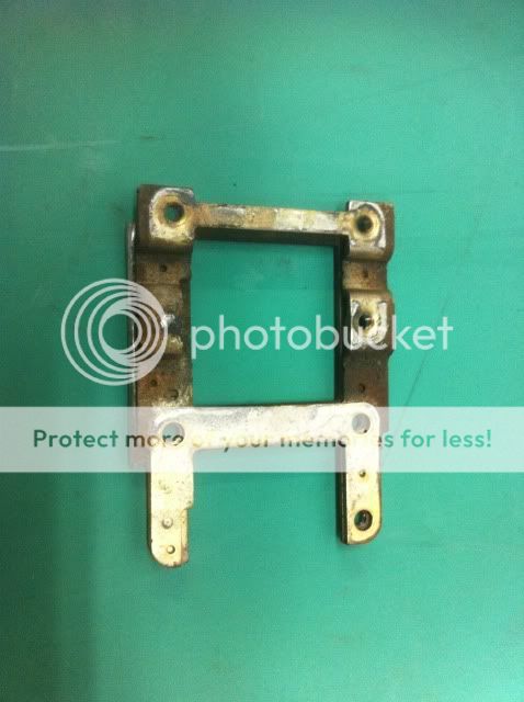
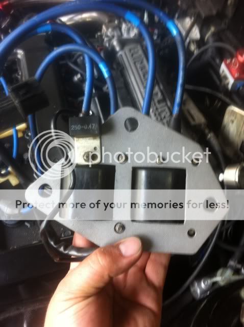
Okay, using a Cyclone manifold, original Cyclone coil pack bracket and Cyclone Transistor plate all these pictures will make sense. If you do not have the Transistor plate, you simply need to make a plate. If you do not have the coil pack bracket, EHMotorsports just showed you in the last post, a HOW-TO on creating one.

Let the pictures begin!

Re-wiring the coil packs, essentially swapping the wiring from the left coils, to the right and vice-versa, leaves the spark plug locations as follows:


Visual on the wires. First photos will be PRE-SWAP (ie original orientation as you might find them fresh from the factory. Pictured is the 1989 Mirage/Colt wiring, likely identical to the 1990 DSM.

Original positions as follows:


MODIFIED locations and wiring schematic, just in case anyone is color blind:


Notice the covers in the background, you have to notice that they have different sized holes for the wiring to come out from the towers, they must be switched side to side.


Final note for the coil wiring towers. Seems Mitsubishi liked to change the nuts that were used between the Mirage/Colt and DSM posts. They used 7mm nuts and 8mm nuts for the smaller of the posts. If you can get 8mm nuts, it will make working on the car much easier, should any wiring ever have to come off again, because what else on this car is 7mm!! 8,10,12,14,17, 22mm .... haha. Saved you the headache of not having brought the correct tool home.


So, you now have the coils wire locations figured out, but you need to disregard the plug wires orientation going over the rocker cover because the NGK Wires are not long enough to achieve proper fitment if you use the coil pack in the stock Cyclone location. Pics will show what you have to do, to make them fit snugly.

First attempt - COULD NOT FIT THE WIRE COVER IN PLACE IN THIS ORIENTATION, but it does look pretty. If you had longer or custom wiring, the old throw back thought to King wires comes up, or a call to NGK, you could use this orientation. Coil pack wiring is still swapped to achieve this.


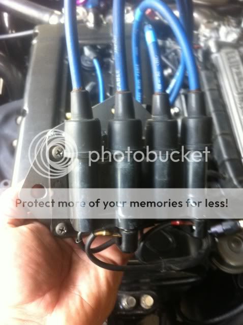
This is the wire orientation I found worked best, and everything fits, including the spark plug wire cover! NOTICE THE WIRE FLIP NEAR THE OIL CAP AREA!! The wires extend straight down after that.


Coil pack nearest the fuel rail. Going from the front terminal to the back, NGK wire #1, then #3.


Coil pack nearest the firewall. Going from the front terminal to the back, NGK wire #4, then #2.


Final outcome with all covers in place.


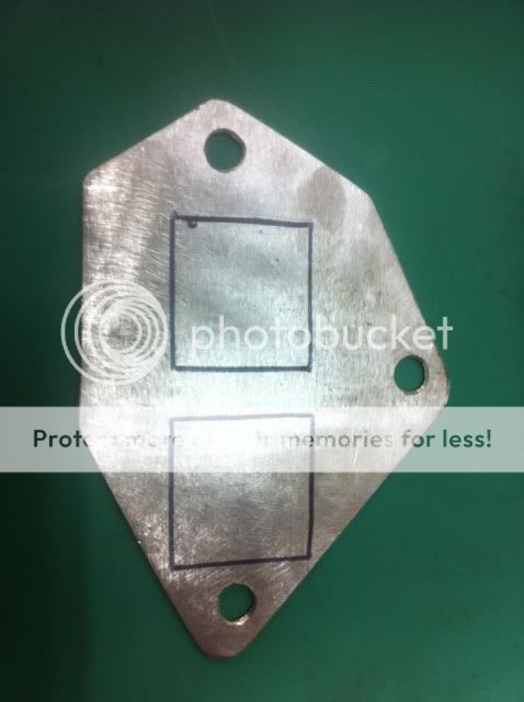
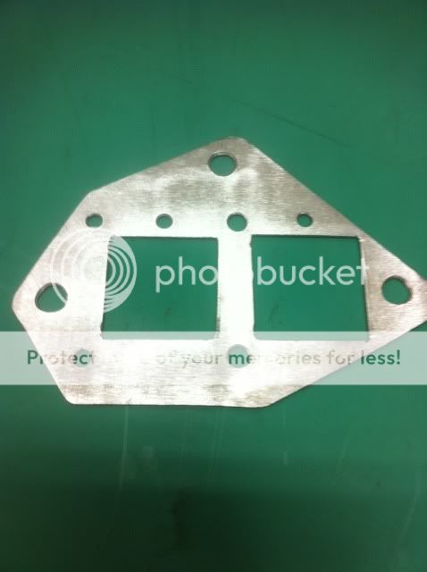
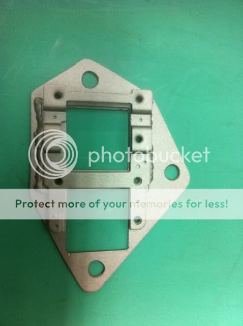
Final Cyclone TRANSISTOR plate modification. Using a 1990 style wiring harness means getting your wires to the top of a transistor plate as would happen using the stock Cyclone wiring orientation, was not going to happen. Decided to aim the Transistor pins down back towards the main engine harness (it gets very close so I cut the plate back and mounted the transistor using the two holes I had already made! Small victory .....


FlyingEagle

Staff member
Joined
Mar 5, 2005
Messages
1,635
Location
THE Ottawa
Pics of the inline filter for the tachometer signal coming from the yellow output wire on the tacho interface.

Bad pic with the sticker intact.


Sticker removed.


Another angle.


The goodies that lie within.


FlyingEagle

Staff member
Joined
Mar 5, 2005
Messages
1,635
Location
THE Ottawa
Just an update with information from bradrs concerning the surface the PTU should/could be contacting if you painted your bracket like I did. I am referring to the PTU bracket and not the rear brace for the intake manifold to block.

Quoting bradrs:
Quoting FlyingEagle:
Good point Brad.

TJ

I painted my Transistor bracket and installed it, much like our guy in this thread.

I saw the base of the transistor/heat sink and figured a clean surface would have to do for the time being.

Wonder where the best places to get that cadmium plating would be?

Is that what they call the coating on most of the metal parts, that look rather yellow?

I'm sure the green stuff is a different coating altogether.

/TJ


I think what was on our car brackets is a cadium plating. Which many places no longer do, due to the environmental concerns. It is toxic, and should not be handled, so it is now only used in applications where nothing else is acceptable.

It has been replaced with several other types of plating, but I don't think any of them work as well as the old cadmium plating overall. I don't know what to suggest as a replacement right now. Some of the zinc coatings people do are mostly decorative, not very protective. Nickel plating looks good, but has its downsides as well. The best sounding substitute for these brackets, from what I have read, may be a tin-zinc.

 
Support Vendors who Support the GVR-4 Community
Boosted Fabrication ECM Tuning ExtremePSI Fuel Injector Clinic Jacks Transmissions JNZ Tuning Kiggly Racing Morrison Fabrications RixRacing RockAuto RTM Racing STM Tuned
Top