The Top Mitsubishi Galant VR-4 Resource

Join the best E39A 1991-1992 Mitsubishi Galant VR-4 community and document your GVR4 journey.

  • Software Upgraded - Reset Your Password to Login
    In order to log in after the forum software change, you need to reset your password. If you don't have access to the email address you used to register your GVR4.org account, you won't be able to reset your password. In that case, follow the instructions here to regain access to the forum.

ECU STUDY.

misterfixit

Well-known member
Joined
Aug 4, 2004
Messages
1,596
Location
Midlands, UK
Hi I was posting with a kinda specific request. I have just gotten my EEprom ecu finally, and as I was not ruushed to get it into the car I wanted to get a project underway I've been mulling over for some while and hopefully give something back to the community.

Lots of people have big involvement in the ecu's and I make no gains about being a program whizz, but as I have some patience and an ecu at my disposal I pulled it down somewhat as I was changing the caps and socketing it.


My goal is to produce a wiring diagram for the ecu, as i think it would be a useful contribution as I don't know of one that exisits yet.


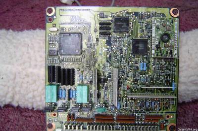
Here is the progress so far on the front side of the board.


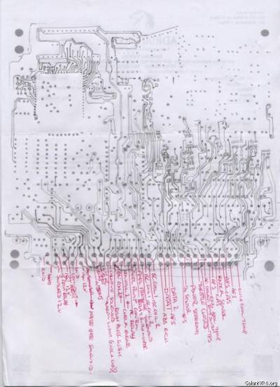
The reason I'm posting is I was hoping someone, or maybe a few people could fill in the gaps. If there are any dead ecus on shelve (unrepairable preferrably) that the microcontroller and the other chips I couldn't see under could be pulled off, I'm kinda asking for some good high resoloution pics of what goes on underneath and the knock board which would be fantastic. Otherwise I'll have to wait and bell the rest of the board with my meter.

The white residue on the board is the conformal coating which can be washed off with contact cleaner!

The board numbber, as seen on the upper pic is e331b989d, this board is also used in us turbo and non turbo ecu's.

Here's the underside,


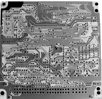
Once I have the rest of the upper side I can overlay the underside and start creating a schematic.

I hope you guys can help, and I hope when complete this helps.

Rich
 

Do you know if this is a multi-layer board? If so, this could be a daunting task. You'd have to use a multimeter and test each port against the others. If it's just a front and back, it shouldn't be as hard.

-Josh
 

Terry Posten

Well-known member
Joined
Dec 16, 2003
Messages
9,009
Location
Davenport, Iowa USA
Yes, this is a multi-layer board. I would like to get a copy of the schematic if anybody has one.
 

misterfixit

Well-known member
Joined
Aug 4, 2004
Messages
1,596
Location
Midlands, UK
no it's only single layer on each side, And NO ball gate arrays, otherwise I'd have not even started.

Rich
 

Mine is definitely only two layers too i.e top and bottom. I started tracing mine out, straight to a circuit diagram. Hadn't thought of drawing the tracks top and bottom first, maybe because I'm no artist and don't have a good enough eye and steady enough hand any more. I doubt if anything I've done would be of much help - I was mostly tracing inputs and outputs, then gave up through lack of further interest. That was on my old dead ECU that died before I found out about the cap leakage problem and has a split in the top of IC5 ... damn!
 

Props to anyone if they have a working schematic. If one were to finish a schematic, ECU modfications could be taken to the next level. Hardware mods could be done on the schematic and then new boards could be ordered. Swapping components could take awhile though.

-Josh
 

jepherz

Staff member
Joined
Aug 8, 2004
Messages
7,877
Location
KC, Missouri
I've never found it to be multi-layer...

People have tried for a long time to get schematics for our ECUs with no luck I believe. The ECUs were all done by Mitsubishi Electric so any connections you have to someone at Mitsubishi Motors don't really do any good.

Looks like a lot of work, keep it up!
 

DarkDevilMMM

Well-known member
Joined
Jun 8, 2001
Messages
4,065
Location
Vacaville, CA
keep up the good work I'll say, but don't mess up, one little error may blow something up.

I would say the easiest way is to get a dead ECU, desolder everything out, clean the board entirely and scan the board that way. I would think it's easier then you have to trace it by hand, I don't know, just me tho. good luck
 

jepherz

Staff member
Joined
Aug 8, 2004
Messages
7,877
Location
KC, Missouri
^^^ I was going to suggest that. Get a dead ECU and attach it with a good heat-gun :)
 

misterfixit

Well-known member
Joined
Aug 4, 2004
Messages
1,596
Location
Midlands, UK
Thats why I was posting, if anyone wants to donate a good picture of a dead ecu board!

Rich
 

gtluke

Well-known member
Joined
Sep 16, 2001
Messages
4,210
Location
dirty jersey
still working on this? found it while searching
i have a spare 90, 91, and 91 eprom computer and a 10MP digital camera. i can take insane clear close up photo's of this i believe. any interest?
i also design electrical systems for a living, but not circuit boards. i could help plot it out in CAD though, but i'm not sure if i would understand everything on the board, but some people at work could help me identify the purpose and function of some of the components.
 

misterfixit

Well-known member
Joined
Aug 4, 2004
Messages
1,596
Location
Midlands, UK
That would be magic. Would you be prepared to pull the components off in the blank areas ion the pics I posted?

Need to make sure the board number is the same.

Rich
 
Support Vendors who Support the GVR-4 Community
Boosted Fabrication ECM Tuning ExtremePSI Fuel Injector Clinic Jacks Transmissions JNZ Tuning Kiggly Racing Morrison Fabrications RixRacing RockAuto RTM Racing STM Tuned
Top