^^^ What he said.
It's best to have a dedicated feed for the system, and use the switch only for switching the system on/off.
What type of relays are you using for this project?
What's the current draw of the meth pump?
click on pic to enlarge
click on pic to enlarge
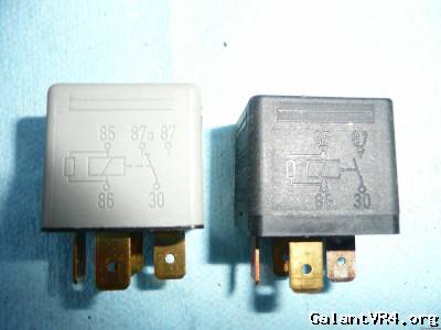
These pictures shows the two most common terminal configurations. 5 pin on the left/4 pin on the right.
... there are many more, so be
very careful how you arrange things.
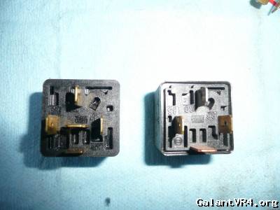
Luckily, the terminal numbers are
mostly standardized.
In addition, most of the quality relays will have a pictogram on the relay body, as well as the terminal numbers next to the terminals on the bottom of the relay.
T30 input (note; can be fed power
or ground)
T87a normally closed contact
When not the relay coil is
not energized, the relay will pass t30 thru this terminal (five pin relay only)
T87 normally open contact
this is the output when the relay coil is energized.
(Whatever you feed t30 will come out here when the relay is "on")
T85 *generally* 12v+ from switch/powersource
T86 *generally* to ground/switchable ground
The last two callouts are for the relay coil and
somewhat interchangeable on many cheap/cheesy/generic relays. If you;re using the good stuff, make t85 power and t86 ground. Note, you can switch either the power or the ground to trigger the relay.
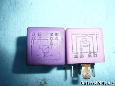
In the pic I posted above it shows a little rectangular box across the coil terminals 85 and 86. That pictorially depicts a resistor (yeah, doesn;t match the "usual" diagram hieroglyph for a resistor, don;t know why they do that)
This is one way to protect the switch from the c.e.m.f. of the collapsing field when the relay is de-energized.
click on pic to enlarge
The arrow with a line in front of it on the t85 leg shows the relay coil is equipped with an anti-flyback diode. This makes the relay coil directionally sensitive. The relay on the right is equipped with a resistor and an anti-flyback diode. It is a high end relay that is used when failure of the upstream switchgear is not an option.
Now, I only mention this because using two relays in series, (with one driving another,) will result in blown fuses/coils/ fused contacts in the primary relay if the collapsing field energy from the second relay is not properly dealt with.
It helps to think of this situation like an ignition system's primary coil dumping it's magnetic field energy into the secondary side of the coil. That system takes 12volts and turns it into 40 thousand volts thru the principle of magnetic induction.
Although you're dealing with smaller coils, the principle is the same, you're just feeding the energy back into the upstream coil here
Turning off the secondary coil collapses the relays coils magnetic field, and that energy heads back up the power line (t85). It's actually
stunning how much voltage there will be, on the order of a couple of thousand volts (if not more!) (that's a
lot of turns of wire in the coil!) This will absolutely zorch the contact points over time, leading to a failure that will render the meth system in-op.
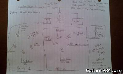
Your best bet is to study the pictogram of the first relay set I posted, and then redraw the diagram, putting the terminals in the correct order and polarity.
I would also add a series of system status led's.
an led for system armed
an led that will show when the system is on/spraying
an led for low fluid level
The instrument cluster has a nice row of automatic transmission indicator blocks stacked vertically in the center of the cluster that are not used in a the manual tranny vr-4s that makes for an excellent location for status indicators.
With the led's in your line of sight, you'll know the system status at a glance. /ubbthreads/images/graemlins/smile.gif